
Upgrading a data center facility to 100G, 400G, or 800G pushes physical space to its limits. Traditional LC duplex patch cords are obsolete in top-of-rack (ToR) switches; they block cooling airflow, exceed bend radius limits, and create cable management nightmares.
The MTP cable solves the density problem.
However, high-density optics are unforgiving. Specifying the wrong polarity, mixing connector genders, mismatching polish types, or compromising on generic components will result in dark links and blown optical budgets.
Here is the exhaustive engineering reality behind MTP technology, how to define your cabling architecture, and how to avoid physical layer bottlenecks.

What Is MTP Cable?
1. What is MTP Cable?
At its core, an MTP® (Multi-Fiber Termination Push-On) cable is a high-density fiber optic cable pre-terminated with MTP connectors.
An MTP cable is a high-density fiber optic patch cord terminated with multi-fiber connectors. Instead of one or two fibers, a single rectangular ferrule houses 8, 12, 16, 24, or up to 72 individual glass fibers.
Instead of holding just one or two optical fibers (like an LC duplex connector), This allows you to plug in a dozen fibers with a single “click,” drastically reducing cable bulk and installation time.
2.MPO Cable vs MTP Cable: Clarifying the Standard
Procurement teams frequently confuse MPO and MTP. They are not interchangeable terms.
-
MPO (Multi-fiber Push-On): The international standard interface (IEC-61754-7 and TIA-604-5). It is a generic term.
-
MTP® (Multi-Fiber Termination Push-On): A registered trademark of US Conec. It is a heavily engineered, premium iteration of the MPO connector.
What is an MPO Cable? MPO (Multi-fiber Push-On) is the international standard interface (IEC-61754-7 and TIA-604-5). It is a generic term.
What is an MTP Cable? MTP® (Multi-Fiber Termination Push-On) is a registered trademark of US Conec. It is a heavily engineered, premium iteration of the MPO connector.
All MTP connectors are MPOs. Not all MPOs are MTPs.

2. MPO vs MTP Connector: What is the Difference?
Hyperscalers and premium colocation providers strictly mandate “Genuine US Conec MTP” to guarantee Insertion Loss (IL) stability. Pushing 400G PAM4 signals through parallel optics leaves zero margin for physical signal degradation. US Conec engineered specific upgrades over generic MPO:
1.Floating Ferrule: Generic MPO ferrules are rigidly fixed. If the cable is bumped, the physical glass connection breaks. The MTP ferrule “floats” inside its housing, maintaining continuous physical contact.
2.Elliptical Guide Pins: Aligning 12 microscopic fiber cores requires guide pins. Generic chamfered pins scrape the plastic housing, generating dust that blocks the light path. MTP uses elliptical stainless steel pins that slide smoothly without creating debris.
3.Metal Pin Clamp: MTP connectors utilize a metal pin clamp with a centered push-spring. This prevents the spring from shifting and crushing the bare fibers during mating.
4.Push-Pull Tabs: For high-density patch panels, extended push-pull tabs allow technicians to extract cables without damaging adjacent active links.

Quick Reference: Generic MPO vs. US Conec MTP®
These mechanical upgrades ensure that MTP maintains ultra-low insertion loss over hundreds of matings, whereas generic MPO often suffers from signal drop due to plastic debris or spring misalignment.
3. MTP Polish Types: APC vs UPC
A critical specification often overlooked is the ferrule polish. This defines the Return Loss (RL)—how much light reflects back into the laser source.
-
UPC (Ultra Physical Contact): The ferrule is polished flat. Used exclusively for Multimode MTP cables.
-
APC (Angled Physical Contact): The ferrule is polished at an 8-degree angle. This forces any reflected light out into the cladding rather than back down the core. Used for Single-Mode MTP cables, and increasingly for high-speed Multimode AI clusters.
Engineering Rule: Never mate an APC connector to a UPC connector. The 8-degree angle will shatter the flat glass of the UPC connector.
4. MTP Cable Color Codes (OS2, OM3, OM4, OM5)
In a densely populated optical distribution frame (ODF), technicians rely on standard color coding to identify cable specifications instantly.

Quick Reference: Fiber Types & Color Codes
5. MTP Fiber Counts: Base-8 vs Base-12 vs Base-16
The fiber count inside the ferrule must match your transceiver architecture to prevent dark (wasted) fibers.
-
Base-12 (12 or 24 Fibers): The legacy backbone. Primarily used for 10G to 40G migrations. However, a 40G QSFP+ transceiver only utilizes 8 fibers (4 Tx, 4 Rx). Using a Base-12 cable leaves 33% of your glass dark.
-
Base-8 (8 Fibers): The dominant standard for QSFP transceivers (40G/100G/200G). It aligns perfectly with 8-fiber transceivers, ensuring 100% fiber utilization across the optical budget.
-
Base-16 & Base-24: The emerging standard for 400G and 800G. Designed for high-lane-count transceivers (OSFP and QSFP-DD) utilized in AI GPU clusters and machine learning fabrics.
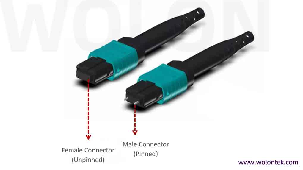
6. MTP Connector Gender: Male vs Female
Mating MTP links requires strict adherence to connector gender.
-
Male MTP (Pinned): Features two steel guide pins.
-
Female MTP (Unpinned): Features two alignment holes.
-
The Rule: Transceivers on network switches are universally Male. Therefore, the MTP patch cord plugging into the switch must be Female. Always mate Male to Female.
7. MTP Cable Polarity: Method A, B, or C?
In an MTP link, polarity is the physical map of the glass. Because MTP connectors mate multiple fibers simultaneously, ensuring the Transmit (Tx) laser precisely hits the Receive (Rx) sensor is critical. If the polarity is wrong, the optical budget might test fine, but the switch will stay dark.
Understanding polarity starts with the connector’s Key. When the key is facing up (Key Up), fibers are numbered 1 to 12 from left to right. When facing down (Key Down), the numbering reverses.
7.1 Method A (Straight-Through)
Method A uses Key Up to Key Down adapters.
-
Mapping: Fiber 1 maps to Fiber 1, Fiber 2 to Fiber 2, etc.
-
The Engineering Bottleneck: Because the trunk cable does not cross the fibers, you must use a “straight” patch cord on one end and a “cross-over” (A-to-B) patch cord on the other. Managing two different types of patch cords in a massive data hall inevitably leads to human error and inventory chaos.
7.2 Method B (The Data Center Standard)
Method B uses Key Up to Key Up adapters.
-
Mapping: The entire fiber array is flipped. Fiber 1 maps to 12, Fiber 2 to 11, etc.
-
The Advantage: This is the undisputed standard for 40G/100G/400G parallel optics. Because the trunk cable handles the flip, you use identical Type B cassettes and Type B patch cords on both ends of the link. This simplifies procurement, deployment, and troubleshooting, making it the default for hyperscale facilities.
7.3 Method C (Pair-Flipped)
Method C uses Key Up to Key Down adapters.
-
Mapping: Adjacent pairs are flipped (1 to 2, 2 to 1, 3 to 4, 4 to 3).
-
The Limitation: This topology mimics legacy duplex logic, originally designed for 10G networks. It cannot directly support 400G parallel transmission (which requires 8 or 16 fibers firing simultaneously). Method C is practically obsolete in modern High-Performance Computing (HPC) clusters.
Polarity Pitfalls: The Engineer’s Checklist
1.Never Mix Standards: Never deploy Method A and Method B inside the same facility. Troubleshooting a mixed-polarity network during a capacity expansion is an absolute nightmare.
2.Check the Adapters: Polarity is not just inside the cable; it is dictated by the mating adapters. You must specify whether you need Key Up to Key Up or Key Up to Key Down when ordering your patch panels.
3.The Base-8 Nuance: 8-fiber systems typically use a modified Method B to perfectly match the 4-Tx / 4-Rx lane logic of QSFP transceivers.
🛠️ Engineering Resource: Fixing a reversed Tx/Rx signal on site can be a nightmare. For a deep dive into troubleshooting flipped pairs and mapping issues, read our complete [MPO Polarity Guide: Common Errors, Case Studies, and Quick Fixes]
8. Types of MTP Cables: Trunk, Breakout, and Conversion
Data center architects utilize three distinct assemblies to route traffic efficiently:
-
MTP Trunk Cables: MTP connectors on both ends. These are the heavy-duty backbones installed in cable trays, establishing permanent links between distribution zones.
👉 Learn how hyperscalers architect these core links in our guide: [Building The Backbone: Why Pre-Terminated MTP/MPO Trunk Cables Are Essential For Hyperscale].
-
MTP Breakout Cables (Harness): An MTP connector on one end breaking out into multiple LC duplex connectors on the other. Used to split a high-capacity switch port (e.g., one 100G port) into individual server connections (e.g., four 25G ports).
👉 To understand port splitting economics, check out [Maximizing Switch Port Density: The Strategic Role Of MPO To LC Breakout Cables]([Insert URL Here]) and avoid common procurement errors with our guide on [Specifying MTP/MPO Breakout Cables: Configurations and Hardware Pitfalls].
-
MTP Conversion Cables: MTP connectors on both ends with varying fiber counts (e.g., converting two 12-fiber trunks into three 8-fiber outputs) to maximize legacy Base-12 cable utilization when upgrading to Base-8 switches.

9. How to Clean and Test MTP Cables
Installing high-density optics without testing guarantees future packet loss.
-
Factory 3D Interferometry: Premium manufacturers laser-scan every ferrule end-face to verify Radius of Curvature, Apex Offset, and Fiber Height. This ensures flawless physical contact.
-
Site Cleaning (Dry vs. Wet): The MTP ferrule has a massive surface area. A single dust particle creates an air gap across all fibers. Technicians must use a dedicated MTP click-cleaner (dry) before mating. For stubborn oils, lint-free wipes with optical solvent (wet) are required.
👉 Master the exact field process by reading our [How to Clean MPO Connectors: The “Inspect Before You Connect” (IBYC) Protocol].
-
Site Testing: Field validation requires an MPO-capable Light Source and Power Meter (LSPM) or an Optical Time-Domain Reflectometer (OTDR) to verify Insertion Loss limits.
Sourcing Factory-Direct MTP Cabling
High-density cabling is the physical foundation of your data center. The precision of a genuine US Conec MTP connector is non-negotiable when mitigating packet loss in 400G/800G environments.
Since 2010, Wolontek has engineered the physical layer of the internet. We bypass trading companies and distribution markups. Operating directly from our Wuhan Optical Valley facilities, our workforce of over 400 optical specialists manufactures strict-tolerance MTP trunk cables, breakout cables, and high-density distribution panels.
We utilize 100% genuine US Conec components and Corning® optical fiber. Every MTP assembly ships with individual 3D Interferometer test reports, guaranteeing the ultra-low insertion loss (Max 0.35dB) required by modern hyperscalers.
📊 Evaluating Asian Suppliers? See our [Top 5 China MPO Fiber Manufacturers (2026 Sourcing Guide)] to understand how to bypass distributor markups safely.
👉 [request a Custom MTP Quote Today] (Button) Get a response from our engineering team within 12 hours. Full 3D interferometer test reports included with every shipment.
What is the difference between MPO and MTP cable?
MPO is the generic international standard for multi-fiber push-on connectors. MTP® is a registered trademark of US Conec representing a premium, highly engineered version of the MPO connector. MTP features mechanical upgrades like a floating ferrule and elliptical guide pins to ensure ultra-low insertion loss in high-speed networks.
Can I plug an MPO connector into an MTP connector?
Yes. Because MTP is an enhanced version built upon the standard MPO interface, they are 100% physically cross-compatible. However, mating a generic MPO with a premium MTP will degrade your overall link performance to the level of the generic MPO component.
What is the difference between Base-8 and Base-12 MTP?
This refers to the number of active glass fibers inside the connector. Base-12 uses 12 fibers and is common for legacy 10G/40G architectures. Base-8 uses exactly 8 fibers and is the modern standard for 40G/100G/200G QSFP transceivers, ensuring 100% fiber utilization without leaving 4 fibers “dark” or wasted.
Why do MTP connectors have different genders?
MTP connectors require precise mechanical alignment for the microscopic glass fibers to mate perfectly. Male (pinned) connectors have two steel guide pins, while Female (unpinned) connectors have two alignment holes. You must always mate a Male connector to a Female connector. (Note: Optical transceivers on switches are always Male).
Can I connect an APC MTP to a UPC MTP?
No. Never do this. An APC (Angled Physical Contact) connector is polished at an 8-degree angle to reduce return loss, while a UPC (Ultra Physical Contact) connector is polished completely flat. Forcing them together will crush the glass cores and permanently destroy both cables.