
MPO/MTP cabling has become a fundamental part of high-density fiber infrastructure, particularly in data centers, enterprise networks, and high-speed optical interconnects. By terminating multiple optical fibers within a single compact connector interface, MPO/MTP assemblies can significantly increase fiber density while simplifying cable management.
However, MPO/MTP cables are not all designed for the same purpose.
MPO trunk cables, breakout cables, harness cables, and patch cords may use similar multi-fiber connector technology, but their construction, fiber mapping, deployment position, and intended applications are different. Selecting the wrong assembly can lead to polarity errors, incompatible connector configurations, excessive optical loss, or unnecessary complexity during installation and maintenance.
This guide explains the major MPO cable types and MTP cable types, including their construction, applications, fiber counts, polarity, connector gender, and selection criteria.
Whether you are designing a new data center cabling system, upgrading an existing network, or specifying custom fiber assemblies, understanding the difference between these cable types is the first step toward building a reliable and scalable optical link.
Quick answer: MPO/MTP trunk cables are primarily used for high-density backbone connections. MPO/MTP breakout cables divide a multi-fiber interface into multiple individual or lower-count connections. Harness assemblies provide a compact, controlled fan-out transition, while MPO/MTP patch cords are generally used for shorter, flexible equipment and panel interconnections.
MPO/MTP Cable Types at a Glance
The easiest way to understand the different MPO/MTP cable types is to start with their primary function within the network.
| MPO Cable Type | Primary Function | Typical Configuration | Common Application |
|---|---|---|---|
| MPO Trunk Cable | High-density backbone interconnection | MPO/MTP to MPO/MTP | Panel-to-panel, rack-to-rack, MDA/HDA backbone |
| MPO Breakout Cable | Splits one multi-fiber interface into multiple connections | MPO/MTP to multiple LC, SC, or MPO/MTP | 100G-to-4x25G, 400G breakout, equipment interconnection |
| MPO Harness Cable | Compact controlled fan-out/transition | MPO/MTP to multiple duplex or multi-fiber connectors | High-density equipment and panel connections |
| MPO Patch Cord | Short flexible interconnection | MPO/MTP to MPO/MTP or other connector combinations | Switch-to-panel, cassette-to-panel, direct equipment connections |
Two cables may both use MPO connectors but have completely different purposes. For example, an MPO trunk is normally designed as a structured backbone assembly, while an MPO patch cord is intended for shorter, more flexible interconnections.
What Are MPO and MTP Cables?
MPO: The Multi-Fiber Connector Interface
MPO stands for Multi-fiber Push-On. It is a multi-fiber connector interface designed to terminate and align multiple optical fibers within a single connector.
The MPO connector family is standardized under IEC 61754-7, which defines the dimensional interface requirements for MPO connectors.
MPO assemblies can be manufactured with different fiber counts, including:
- MPO-8
- MPO-12
- MPO-16
- MPO-24
The appropriate configuration depends on the optical transceiver, lane architecture, fiber utilization, polarity, and overall cabling design.
MPO technology is particularly useful in high-density environments because multiple optical channels can be managed through a single connector interface rather than using a separate connector for every fiber pair.
MTP®: A High-Performance MPO Connector
MTP® is a registered trademark of US Conec and refers to its high-performance MPO connector solution.
Therefore, MPO and MTP® should not technically be treated as completely interchangeable terms:
MPO is the standardized connector family; MTP® is a specific high-performance MPO connector technology.
MTP® connectors are designed to comply with applicable MPO interface requirements while incorporating design features intended to improve mechanical and optical performance.
Throughout this guide, MPO/MTP is used when discussing cable assemblies that may use either compliant MPO connectors or MTP® connectors. When a connector-specific characteristic matters, MPO and MTP® are distinguished explicitly.
This distinction is particularly important for engineering specifications and procurement documents. If a project specifically requires genuine MTP® components, the requirement should be stated explicitly rather than assuming that every MPO assembly is an MTP® assembly.
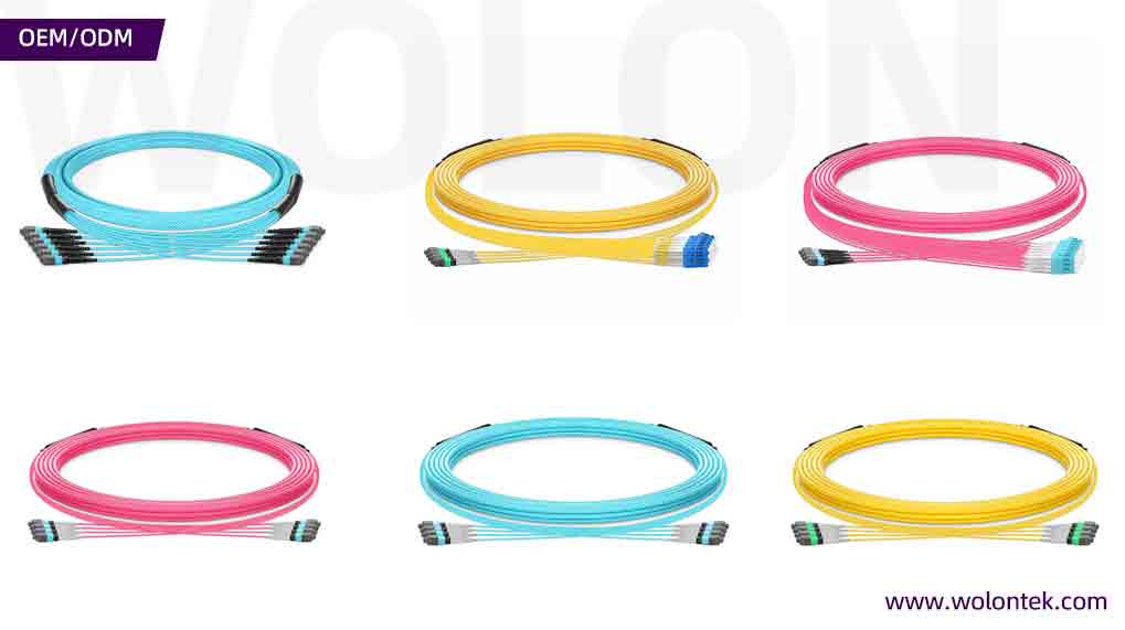
Depending on the application, MPO-based assemblies can use different fiber counts, including:
- MPO-8
- MPO-12
- MPO-16
- MPO-24
The appropriate fiber count depends on the transceiver architecture, optical lane configuration, cabling design, and desired fiber utilization.
MPO technology is particularly important in modern data centers because parallel-optics applications can use multiple fibers simultaneously rather than relying exclusively on traditional duplex fiber connections.
For example, a parallel-optics interface may use separate fibers for multiple transmit and receive lanes. This makes MPO/MTP connectivity well suited to high-density Ethernet and data-center interconnect architectures.
MPO vs MTP: Are They the Same?
One of the most common sources of confusion is the difference between MPO and MTP.
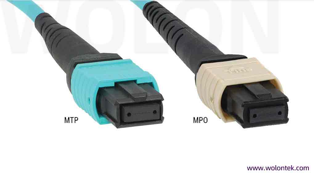
MPO is the generic connector family, while MTP® is a registered US Conec brand of high-performance MPO connector.
US Conec states that its MTP® connector complies with MPO connector standards and is intermateable with compliant generic MPO-style connectors. US Conec also describes MTP® as a high-performance MPO connector engineered for improved mechanical and optical performance.
Therefore:
MTP® is an MPO connector, but MPO is not necessarily MTP®.
In technical specifications, it is better to state the actual connector requirement rather than using MPO and MTP as completely interchangeable product names.
For projects that specifically require genuine US Conec MTP® components, the procurement specification should identify that requirement explicitly.
1. MPO/MTP Trunk Cable
What Is an MPO Trunk Cable?
What Is an MPO/MTP Trunk Cable?
An MPO/MTP trunk cable is a factory-terminated multi-fiber cable assembly designed primarily for high-density backbone and structured cabling connections.
A typical trunk cable has a multi-fiber connector at each end:
MPO/MTP → Multi-Fiber Cable → MPO/MTP
The cable may contain 8, 12, 16, 24, or higher fiber counts depending on the application.
Unlike a simple equipment patch cord, an MPO/MTP trunk cable is commonly used as part of the fixed cabling infrastructure connecting distribution areas, patching systems, racks, or zones within a data center.
Typical MPO/MTP Trunk Cable Applications
MPO/MTP trunk cables are commonly deployed for:
- MDA-to-HDA backbone connections
- HDA-to-EDA connections
- Rack-to-rack backbone links
- Patch-panel-to-patch-panel connections
- MPO cassette interconnection
- High-density data center cabling
- Spine-leaf network infrastructure
- Structured fiber distribution systems
A simplified deployment can look like:
MDA → MPO/MTP Trunk → HDA → MPO/MTP Cassette → Equipment
The trunk cable provides the high-density backbone, while cassettes, patch cords, or breakout assemblies provide the required equipment-level interface.
Why Use an MPO/MTP Trunk Cable?
Trunk assemblies are useful when a network requires:
- High fiber density
- Reduced cable congestion
- Factory-terminated connections
- Repeatable fiber mapping
- Scalable backbone infrastructure
- Faster field deployment
- Organized structured cabling
Pre-terminated trunk assemblies can also reduce the amount of field termination required during installation, which can improve deployment consistency when the cable configuration is properly engineered in advance.
How to Specify an MPO/MTP Trunk Cable
A complete trunk cable specification should normally identify:
- Fiber count
- Fiber type
- MPO or MTP® connector
- Connector gender
- Polarity
- Connector configuration
- Cable length
- Cable diameter
- Jacket type
- Insertion-loss grade
- Installation environment
For example:
24F OM4 MTP® trunk cable, Method B, male-to-male, LSZH, 30 m
is significantly more useful as a procurement specification than:
24F MPO cable
WolonFiber product link:
See WolonFiber MTP/MPO Trunk Cables
2. MPO/MTP Breakout Cable
What Is an MPO/MTP Breakout Cable?
An MPO/MTP breakout cable converts one multi-fiber connection into multiple smaller connection interfaces.
A typical architecture is:
MPO/MTP → Fan-Out Transition → Multiple Connectors
For example:
MPO-8 → 4 × LC Duplex
or:
MPO-16 → 8 × LC Duplex
The exact configuration depends on the optical interface and the number of active fibers required.
Breakout assemblies are particularly useful when a high-density parallel-optics interface needs to connect to multiple lower-speed duplex interfaces.
Common MPO/MTP Breakout Applications
Typical applications include:
- 40G-to-10G migration
- 100G-to-25G connectivity
- 400G breakout architectures
- Switch port breakout
- Spine-to-leaf connections
- Server aggregation
- High-density equipment interconnection
- Parallel-optics migration
For example, a 100G SR4 optical interface uses eight optical fibers arranged as four transmit and four receive fibers. A suitable Base-8 breakout architecture can therefore divide the eight-fiber interface into four duplex links.
The exact breakout configuration must always be matched to the transceiver manufacturer’s optical lane specification.
MPO/MTP Breakout vs Trunk
The difference is straightforward:
A trunk cable carries a multi-fiber connection from one structured-cabling point to another.
A breakout cable divides a multi-fiber connection into multiple smaller connection paths.
A trunk preserves the multi-fiber architecture across the cable.
A breakout introduces a deliberate transition between the multi-fiber interface and the destination interfaces.
WolonFiber product link:
See WolonFiber MTP/MPO Breakout Cables
3. MPO/MTP Harness Cable
What Is an MPO/MTP Harness Cable?
The term MPO/MTP harness cable is not used with exactly the same meaning by every manufacturer.
In practical fiber-optic applications, a harness assembly generally refers to a compact, factory-terminated fan-out assembly that provides a controlled transition from one MPO/MTP connector to multiple individual or multi-fiber connectors.
A typical structure is:
MPO/MTP → Short Fan-Out → Multiple Connectors
For example:
MPO-8 → 4 × LC Duplex
The important characteristic is the controlled physical organization of the individual legs.
Harness assemblies are often designed with defined leg lengths and compact fan-out structures to simplify routing within racks, panels, and equipment areas.
Typical MPO/MTP Harness Applications
Harness assemblies can be used for:
- High-density patch panels
- MPO cassettes
- Equipment interconnections
- Server and switch connections
- Rack-level transitions
- Compact fan-out applications
- Structured cabling transition points
MPO/MTP Harness vs Breakout Cable
The terms breakout, fanout, harness, and sometimes hydra may overlap in manufacturer terminology.
A practical distinction is:
Breakout cable emphasizes the function of dividing a multi-fiber connection.
Harness cable emphasizes the physical construction of the fan-out assembly.
Therefore, a harness can effectively be a specialized type of breakout or fan-out assembly depending on the manufacturer’s product definition.
For engineering and procurement, it is better to specify the actual connector mapping, fiber count, leg count, leg length, polarity, and connector gender than to rely on the product name alone.
4. MPO/MTP Patch Cord
What Is an MPO/MTP Patch Cord?
An MPO/MTP patch cord is a fiber-optic cable assembly used primarily for shorter, flexible interconnections between equipment, patch panels, cassettes, and other optical interfaces.
A typical configuration is:
MPO/MTP → Fiber Cable → MPO/MTP
Compared with a structured backbone trunk, the primary role of a patch cord is flexible interconnection.
MPO/MTP patch cords can be supplied in different fiber counts and configurations, including Base-8, Base-12, Base-16, and Base-24 assemblies.
Typical MPO/MTP Patch Cord Applications
MPO/MTP patch cords can be used for:
- Switch-to-panel connections
- Equipment-to-panel connections
- Cassette-to-panel connections
- Switch-to-switch connections
- Short rack-level connections
- High-density patching
- Direct MPO/MTP equipment connections
Because patch cords are more likely to be handled, disconnected, or replaced during network changes, cable flexibility, connector accessibility, bend performance, and cable management are important considerations.accessibility can be more important than the characteristics required for a permanent backbone cable.
WolonFiber product link:
See WolonFiber MTP/MPO Patch Cord
MPO/MTP Cable Types: Direct Comparison
The four main categories can be compared as follows:
| Feature | MPO/MTP Trunk | MPO/MTP Breakout | MPO/MTP Harness | MPO/MTP Patch Cord |
|---|---|---|---|---|
| Primary role | Backbone | Fiber transition/splitting | Controlled fan-out | Flexible interconnection |
| Typical structure | MPO/MTP to MPO/MTP | MPO/MTP to multiple connectors | MPO/MTP to multiple connectors | MPO/MTP to MPO/MTP or other connectors |
| Fiber density | High | High to multiple lower-density links | High to multiple lower-density links | Moderate to high |
| Typical deployment | MDA/HDA, panel-to-panel | Equipment breakout | Equipment/panel transition | Equipment and patching |
| Typical length | Short to long | Short to moderate | Usually controlled/short | Usually short |
| Breakout function | No | Yes | Usually | No |
| Backbone use | Primary | Supporting | Supporting | Limited |
| Flexibility requirement | Moderate | Moderate | Controlled | High |
The simplest way to remember the distinction is:
- Trunk = backbone
- Breakout = splitting
- Harness = controlled fan-out
- Patch cord = flexible interconnection
MPO/MTP Fiber Counts: 8, 12, 16 and 24 Fibers
Fiber count is one of the most important variables when selecting an MPO/MTP assembly.
However, higher fiber count does not automatically mean better performance.
The fiber count should be determined by the optical architecture of the network.
MPO-8 / Base-8
An eight-fiber configuration is widely used for parallel-optics architectures requiring eight active fibers.
A common arrangement is:
4 Tx + 4 Rx = 8 fibers
This makes Base-8 assemblies particularly useful for certain 40G and 100G parallel-optics applications.
Because all eight fibers can be active in the appropriate architecture, Base-8 can provide efficient fiber utilization.
MPO-12 / Base-12
MPO-12 is a widely deployed multi-fiber format.
It can support different network architectures, including parallel-optics and structured cabling systems using cassette-based connectivity.
However, the number of physically available fibers should not be confused with the number of fibers actively used by a specific optical interface.
For example, if an application requires only eight active fibers within a 12-fiber assembly, four fibers may remain unused in that particular link architecture.
This is one reason why fiber utilization should be evaluated during network design.
MPO-16 / Base-16
MPO-16 provides sixteen fibers and is particularly relevant to higher-density parallel-optics architectures.
An example configuration is:
8 Tx + 8 Rx = 16 fibers
This makes Base-16 assemblies suitable for optical architectures requiring eight parallel transmit and eight parallel receive fibers, subject to the specific transceiver design.
MPO-24 / Base-24
MPO-24 provides 24 fibers in a single high-density connector interface.
It can be used for:
- High-density structured cabling
- Backbone applications
- Fiber aggregation
- High-count breakout architectures
- Specific high-density equipment interfaces
The correct fiber count should always be determined from the complete link architecture rather than simply choosing the highest available count.
MPO/MTP Cable Polarity
Polarity is one of the most important technical considerations in MPO/MTP cabling.
A fiber link must maintain the correct relationship between transmit and receive channels from one end of the system to the other.
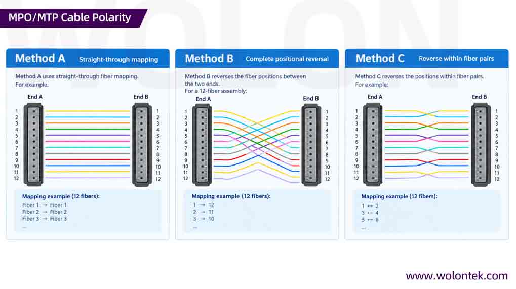
For traditional MPO polarity systems, three commonly referenced methods are:
- Method A
- Method B
- Method C
Method A
Method A uses straight-through fiber mapping.
For example:
Fiber 1 → Fiber 1
Fiber 2 → Fiber 2
Fiber 3 → Fiber 3
and so forth.
Method B
Method B reverses the fiber positions between the two ends.
For a 12-fiber assembly:
1 → 12
2 → 11
3 → 10
and so forth.
This produces a complete positional reversal.
Method C
Method C reverses the positions within fiber pairs.
For example:
1 ↔ 2
3 ↔ 4
5 ↔ 6
and so forth.
The appropriate polarity method depends on the complete cabling architecture, including the transceiver interfaces, adapter orientation, cassette design, and patching strategy.
Therefore, polarity should never be selected independently.
The correct MPO/MTP polarity is a system-level design decision.
MPO/MTP Connector Gender: Pinned vs Unpinned
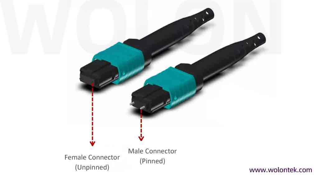
MPO/MTP assemblies can also be specified according to connector gender.
A male connector has guide pins.
A female connector does not have guide pins.
The two ends must be mechanically compatible with the mating components.
This is particularly important for direct connections to active optical transceivers, because the transceiver interface may determine whether a pinned or unpinned connector is required.
When specifying an MPO/MTP cable, connector gender should therefore be stated explicitly.
A complete specification might look like:
16F OM4 MTP® trunk cable, Method B, male-to-female, 15 m
rather than simply:
16F MTP cable
This level of detail reduces the risk of ordering an assembly that is physically incompatible with the intended link.
MPO/MTP Cable Types and Fiber Type
MPO/MTP assemblies are available with both multimode and single-mode fiber.
Multimode Fiber
Common multimode fiber types include:
- OM3
- OM4
- OM5
These fibers are widely used in short-distance data center and enterprise applications.
The appropriate multimode grade depends on the transceiver specification, transmission distance, wavelength, and required link performance.
Single-Mode Fiber
OS2 single-mode fiber is commonly used for longer-distance optical transmission and applications where single-mode transceivers are specified.
The fiber type should always match the optical module.
A physically compatible MPO connector does not guarantee optical compatibility.
MPO/MTP Insertion Loss and Link Budget
Another critical factor is insertion loss.
Every connector and mating interface introduces some amount of optical loss. When multiple MPO/MTP connections are included in a channel, the total connector loss can become an important part of the optical link budget.
A complete link-budget evaluation should consider:
- Fiber attenuation
- Connector insertion loss
- Adapter loss
- Number of mating interfaces
- Splice loss, if applicable
- Transceiver optical budget
- Link distance
This is particularly important for high-speed optical systems with tighter power margins.
For this reason, “low-loss MPO” should not be treated as a marketing phrase alone. The actual specified insertion-loss performance should be verified against the project’s requirements.
How to Choose the Right MPO/MTP Cable Type
The correct cable type should be selected by working backward from the network architecture.
Step 1: Identify the Equipment Interface
First determine what interfaces exist at both ends:
- MPO/MTP
- LC duplex
- SC
- Other multi-fiber connectors
- Proprietary equipment interfaces
If both ends require a multi-fiber connection, a trunk or patch cord may be appropriate.
If one multi-fiber interface must connect to several individual ports, a breakout or harness assembly may be required.
Step 2: Determine the Optical Architecture
Identify:
- Transmission speed
- Transceiver type
- Number of optical lanes
- Tx/Rx fiber requirements
- Wavelength
- Transmission distance
Do this before selecting fiber count.
Step 3: Determine Fiber Count
Based on the optical architecture, determine whether the system requires:
- 8 fibers
- 12 fibers
- 16 fibers
- 24 fibers
- Another configuration
The objective is not simply to maximize fiber count. It is to achieve the appropriate combination of fiber utilization, scalability, density, and compatibility.
Step 4: Determine Polarity
Specify the required:
- Method A
- Method B
- Method C
or provide the exact fiber mapping.
For complex systems, an explicit fiber mapping can be preferable to relying only on a polarity label.
Step 5: Determine Connector Gender
Confirm:
- Male / pinned
- Female / unpinned
for each end of the assembly.
This should be checked against the actual transceiver, adapter, cassette, or mating connector.
Step 6: Select Fiber Type
Choose the appropriate:
- OM3
- OM4
- OM5
- OS2
based on the optical module and transmission requirements.
Step 7: Verify Optical Performance
Check:
- Maximum insertion loss
- Return loss
- Fiber attenuation
- Connector performance
- Total channel loss
The cable assembly should be evaluated as part of the complete optical channel.
Step 8: Match the Cable Construction to the Environment
Depending on the installation, the cable may require:
- LSZH
- OFNP
- OFNR
- Plenum-rated construction
- Riser-rated construction
- Indoor/outdoor construction
- High-density cable construction
- Bend-insensitive fiber
Jacket and flame-rating requirements should be determined according to applicable building codes and project specifications.
Common MPO/MTP Cable Selection Mistakes
1. Treating All MPO/MTP Cables as the Same
A trunk cable is not simply a longer patch cord.
A breakout cable is not simply a trunk cable with different connectors.
The assemblies are engineered for different positions and functions within the optical network.
2. Selecting Fiber Count Before the Transceiver
Starting with:
“I need a 24-fiber MPO cable.”
does not provide enough information.
A better approach is:
“What optical interface am I connecting, and how many fibers does that interface require?”
Then select the appropriate fiber count and mapping.
3. Ignoring Polarity
A cable can have the correct connector, fiber count, and length while still producing a failed optical link if the fiber mapping is incorrect.
Polarity must therefore be considered during system design.
4. Ignoring Connector Gender
Pinned and unpinned MPO/MTP connectors are not universally interchangeable.
The connector gender must match the mating interface.
5. Assuming “MPO” Automatically Means “MTP®”
MTP® is a specific branded MPO connector solution.
If a project requires genuine MTP® components, that requirement should be stated explicitly in the specification.
6. Treating “Harness” and “Breakout” as Universal Terms
Different manufacturers may use breakout, fanout, harness, or hydra terminology differently.
The safest specification describes the actual:
Connector → Fiber Count → Mapping → Connector → Leg Configuration
rather than relying solely on a product category name.
MPO/MTP Cable Types in Data Center Structured Cabling
MPO/MTP assemblies are most effective when each cable type is assigned a clear role within the structured cabling architecture.
A simplified example is:
Main Distribution Area (MDA)
↓
MPO/MTP Trunk Cable
↓
Horizontal Distribution Area (HDA)
↓
MPO/MTP Trunk / Breakout / Cassette
↓
Equipment Distribution Area (EDA)
↓
MPO/MTP Patch Cord / Harness
↓
Active Equipment
The exact topology varies by facility and network architecture, but the principle remains the same:
Use trunk assemblies for high-density backbone infrastructure and transition assemblies where the multi-fiber architecture needs to be converted into the required equipment interface.
This approach helps maintain predictable fiber routing and simplifies future expansion.
MPO/MTP Cable Types for 40G, 100G, 400G and Higher-Speed Networks
As optical Ethernet speeds increase, MPO/MTP cable selection becomes increasingly dependent on the transceiver’s lane architecture.
Examples include:
| Application | Example Optical Architecture | Potential MPO/MTP Configuration |
|---|---|---|
| 40G SR4 | 4 Tx + 4 Rx | Base-8 |
| 100G SR4 | 4 Tx + 4 Rx | Base-8 |
| 400G SR8 | 8 Tx + 8 Rx | Base-16 |
| High-density structured cabling | Application dependent | Base-8 / 12 / 16 / 24 |
These examples should not be interpreted as universal prescriptions.
The transceiver manufacturer’s technical specification should always take precedence when determining fiber count, connector configuration, polarity, and optical requirements.
This becomes increasingly important for 400G, 800G, and future high-speed architectures, where different optical technologies may use different combinations of parallel fibers, wavelengths, single-mode or multimode transmission, and connector formats.
MPO vs MTP: What Should You Specify?
For a technical procurement document, avoid specifications that simply state:
“MPO/MTP cable required.”
A more complete specification should identify:
- Connector type
- MTP® requirement, if applicable
- Fiber count
- Fiber type
- Connector gender
- Polarity
- Cable length
- Jacket type
- Insertion-loss requirement
- Intended transceiver/application
For example:
24F OM4 MTP® trunk cable, Method B, male-to-female, LSZH, 20 m, low-loss configuration
provides substantially more useful information than:
24F MPO cable
The more precise the specification, the lower the risk of receiving a physically compatible but functionally incorrect assembly.
Which MPO/MTP Cable Type Should You Choose?
Use the following decision framework when selecting an assembly.
Choose an MPO/MTP Trunk Cable When:
- You are building a high-density backbone;
- You need to connect distribution areas;
- You need panel-to-panel or rack-to-rack connectivity;
- You want factory-terminated structured cabling;
- You need a scalable multi-fiber infrastructure.
Choose an MPO/MTP Breakout Cable When:
- One MPO/MTP interface must connect to multiple ports;
- You need to split parallel optical lanes;
- You are connecting MPO/MTP to LC or another lower-density interface;
- You are implementing a port breakout architecture.
Choose an MPO/MTP Harness Cable When:
- You need a compact fan-out assembly;
- Individual leg lengths must be controlled;
- Rack space is limited;
- You need an organized transition between multi-fiber and individual connections.
Choose an MPO/MTP Patch Cord When:
- You need a short flexible connection;
- You are connecting equipment to a panel;
- You are connecting MPO/MTP cassettes;
- You need a direct MPO/MTP equipment interconnection;
- The connection may be changed during network maintenance.
MPO/MTP Cable Types FAQ
What are the main MPO/MTP cable types?
The four major categories discussed in this guide are MPO/MTP trunk cables, breakout cables, harness cables, and patch cords.
They serve different roles within a fiber-optic network.
What is the difference between an MPO trunk cable and an MPO breakout cable?
An MPO trunk cable normally maintains a multi-fiber connection between two structured-cabling points.
An MPO breakout cable divides one multi-fiber interface into multiple smaller connection paths.
In simple terms:
Trunk = backbone
Breakout = transition/splitting
Is an MPO harness the same as an MPO breakout cable?
Not always.
The terminology varies among manufacturers.
“Breakout” generally describes the function of dividing a multi-fiber connection, while “harness” often describes the physical fan-out construction.
Always verify the actual connector configuration and fiber mapping.
What is an MPO/MTP patch cord?
An MPO/MTP patch cord is a relatively short fiber assembly used for flexible interconnection between equipment, panels, cassettes, or other optical interfaces.
Is MTP the same as MPO?
No.
MTP® is a specific high-performance MPO connector solution developed by US Conec.
MPO refers to the standardized multi-fiber connector family.
MTP® connectors are designed to comply with applicable MPO interface requirements, but not every MPO connector is an MTP® connector.
What MPO/MTP fiber counts are commonly used?
Common configurations include:
MPO-8
MPO-12
MPO-16
MPO-24
The correct choice depends on the optical architecture, transceiver, fiber utilization, and structured cabling design.
Does MPO/MTP polarity matter?
Yes.
Polarity determines how individual fibers are mapped between the two ends of the optical link.
The traditional MPO polarity methods are A, B, and C. The correct method depends on the complete cabling architecture.
Does MPO/MTP connector gender matter?
Yes.
MPO/MTP connectors may be pinned or unpinned, and the mating components must be mechanically compatible.
Connector gender should therefore be specified when ordering an assembly.
Can MPO/MTP cables be customized?
Yes.
Custom MPO/MTP assemblies can be specified according to application requirements such as:
Fiber count
Fiber type
Connector type
Connector gender
Polarity
Cable length
Fan-out length
Jacket type
Cable diameter
Insertion-loss performance
For complex data center deployments, providing the complete connector and fiber mapping is recommended.
Final Takeaway
The right MPO/MTP cable type depends on the role the assembly performs within the optical network.
MPO/MTP trunk cables provide the high-density backbone.
MPO/MTP breakout cables divide multi-fiber interfaces into multiple connection paths.
MPO/MTP harness cables provide compact, controlled fan-out transitions.
MPO/MTP patch cords provide flexible equipment and panel interconnections.
However, selecting the cable type is only the beginning.
A reliable MPO/MTP link also requires the correct combination of:
Fiber count + fiber type + connector type + connector gender + polarity + insertion loss + cable length + cable construction + installation environment
For high-speed data center applications, these parameters should be engineered together rather than selecting a cable based solely on the MPO or MTP connector name.
WolonFiber provides customized MPO/MTP fiber assemblies for data center and high-density optical networking applications, including trunk, breakout, harness, and patch cord configurations. Assemblies can be specified according to fiber count, fiber type, connector configuration, polarity, cable length, and installation requirements.