
You have a 100G or 400G core switch. You have 25G or 100G server NICs. To bridge the bandwidth mismatch without buying intermediary Top of Rack (ToR) switches, you must physically split the parallel optic ports.
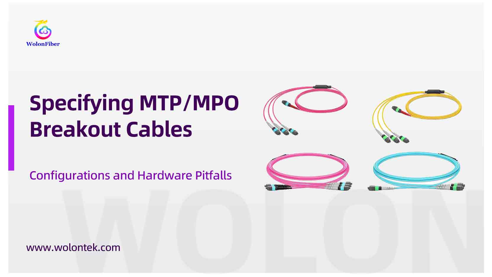
The hardware required is an MTP/MPO to LC breakout cable (or MTP/MPO harness). It takes a multi-fiber connector at the switch interface, runs through a furcation unit, and splits into discrete duplex LC connectors at the server end.
Avoiding breakout cable pitfalls is step one. To ensure your entire optical link—from the core switch down to the server rack—is perfectly matched in terms of polarity, gender, and fiber count, you must understand the core principles outlined in our [Ultimate Guide to MTP Cables].
Specifying this cable incorrectly results in stranded assets, compromised rack airflow, or immediate optical link failure. Here are the exact engineering specifications required to procure breakout cabling for high-density environments.
Before diving into the complex port bifurcation pitfalls, ensure your infrastructure team is aligned on the fundamental optical architectures detailed in our [Ultimate Guide to MTP/MPO Breakout Cables].
1. Port Splitting Geometry: Matching the Transceiver
Breakout cables are not one-size-fits-all. The physical fiber count must precisely match the parallel optical lanes of your active switch transceivers.
Standard Spine-Leaf configurations require the following optical mapping:
100G to 4x 25G: A single 100GBASE-SR4 (QSFP28) transceiver maps to four 25GBASE-SR (SFP28) server ports. Requires an 8-fiber MPO to 4x LC Duplex breakout.
40G to 4x 10G: A 40GBASE-SR4 (QSFP+) maps to four 10GBASE-SR (SFP+) ports. Requires an 8-fiber MPO to 4x LC Duplex breakout.
400G to 4x 100G: A 400GBASE-DR4 (QSFP-DD) maps to four 100GBASE-DR (QSFP28) links. Requires a 16-fiber MPO to 4x LC Duplex breakout.
 Ensure End-to-End Compatibility
Sourcing transceivers and breakout cables from separate vendors introduces optical budget risks and potential finger-pointing during deployment failures. Wolontek manufactures both strict-tolerance Optical Transceivers (QSFP28/QSFP-DD) and the exact Base-8/Base-16 MPO Harnesses required to link them.

2. Hardware Pitfalls: Where Procurement Fails
When submitting a Bill of Materials (BOM), failing to specify the following mechanical details will compromise the physical layer.
Failure Point 1: Deploying Base-12 for Parallel Optics
Parallel optic transceivers (like SR4) use 4 fibers to transmit (Tx) and 4 fibers to receive (Rx). This equals 8 active fibers. If procurement orders a standard 12-fiber MPO breakout cable, the central 4 fibers remain dark. You are paying for 33% more glass than the transceiver can physically use.
The Fix: Always specify Base-8 MPO breakout cables for 40G/100G parallel links to guarantee 100% fiber utilization.
Failure Point 2: Generic MPO on PAM4 Networks
400G and 800G networks use PAM4 modulation, resulting in a strictly limited optical budget. High Insertion Loss (IL) translates directly to bit errors. A generic MPO connector uses a fixed MT ferrule. Any lateral tension on the cable can cause ferrule separation and an immediate IL spike.
The Fix: Specify an MTP® breakout. Engineered by US Conec, the MTP connector features a floating ferrule and elliptical guide pins. This maintains perfect physical mating under mechanical load, holding insertion loss strictly below the 0.35dB threshold.
Failure Point 3: Equal Leg Lengths (Airflow Blockage)
An off-the-shelf breakout cable features LC legs of identical lengths. If your servers occupy U10, U11, and U12 in the rack, plugging in equal-length legs generates excess cable slack. This slack bundles in front of the server chassis, blocking exhaust fans and causing thermal alarms.
The Fix: Specify staggered legs. Measure the Rack Unit (RU) spacing, and have the manufacturer cascade the LC legs (e.g., 0.5m, 0.8m, 1.1m). This provides a zero-slack installation, bypassing the need for horizontal cable managers.

3. Securing Custom Cable Manufacturing
Sourcing staggered, Base-8 MTP breakout cables through regional distributors typically introduces unacceptable lead times, as these are highly customized assemblies. High-density deployments require direct manufacturer integration.
Wolontek engineers and manufactures precision optical assemblies directly for enterprise data centers.
Operating three dedicated production facilities with a workforce of 100+ optical specialists, we build MTP breakout cables to exact RU specifications. Every MTP ferrule undergoes 3D interferometry testing and end-face inspection in our cleanrooms to validate the optical budget before shipping.
Supplying optical communication infrastructure to over 80 countries, our manufacturing processes comply strictly with ISO9001, TLC, CE, RoHS, and FCC standards.

 Require custom staggered lengths for your next build?
Submit your switch port configurations and RU spacing directly to the Wolontek engineering team to receive a precise BOM and production quote.
Submit Your Port Config & RU Spacing
FAQ: MTP/MPO Breakout Cable Specifications
Q1: What gender should the MPO connector be when connecting to a switch transceiver?
A: Active optical transceivers (such as QSFP28, QSFP-DD, or OSFP) are manufactured with pinned (male) MPO ports. Therefore, the MPO connector on your breakout cable must always be unpinned (female). Attempting to force a pinned cable into a pinned transceiver will permanently shatter the optical lenses inside the switch hardware.
Q2: What is the correct polarity for a standard 100G to 4x 25G breakout?
A: For mapping a parallel optic transceiver down to discrete duplex LC ports, the industry standard is Type B polarity (often referred to as Method B). This ensures that the Tx (transmit) lanes from the switch perfectly align with the Rx (receive) lanes on the server NICs without requiring you to manually cross fibers in the field.
Q3: Can I use a single-mode (OS2) breakout cable with my existing SR4 transceivers?
A: No. SR4 (Short Reach) transceivers utilize 850nm VCSEL lasers and must be paired exclusively with Multimode fiber (OM3 or OM4). If you are using DR4 or PLR4 (Long Reach) transceivers, you must specify Single-mode (OS2) breakout cables with APC (Angled Physical Contact) polishes to prevent severe reflectance.
Q4: How do I calculate the correct staggered leg lengths for my rack?
A: Do not guess the measurements. Determine exactly where your furcation bracket will be mounted (typically the Top of Rack). Then, list the specific Rack Unit (RU) position of each server NIC below it. When you provide this RU list, Wolontek’s engineering team will calculate the exact cascading lengths required for a zero-slack installation and manufacture them directly in our cleanroom facilities.