
By the Wolontek Engineering Team | Data Center Architecture & ROI
Let’s talk about switch economics.
If you are deploying a modern Spine-Leaf architecture, you already know that high-spec core and spine switches are massive capital expenditures (CAPEX). A single 100G or 400G port on a top-tier switch represents a significant financial investment.
Leaving that port underutilized—or buying additional low-density ToR (Top of Rack) switches just to accommodate 10G or 25G legacy servers—is financially irresponsible. The goal of any network architect during the hardware selection phase is to drive the cost per Gbps down to the absolute minimum.
The most effective mechanical tool to achieve this financial metric is the MPO to LC breakout cable.
Here is a hard look at the engineering and financial realities of using breakout cabling in high-density environments.
The Financial Model: Port Splitting over Switch Stacking
In a standard ToR or End of Row (EoR) deployment, server NICs (Network Interface Cards) rarely require the full 100G or 400G bandwidth of the uplink switch port. Instead of buying a dedicated 48-port 25G switch, architects can utilize a high-density 100G switch and split the ports.
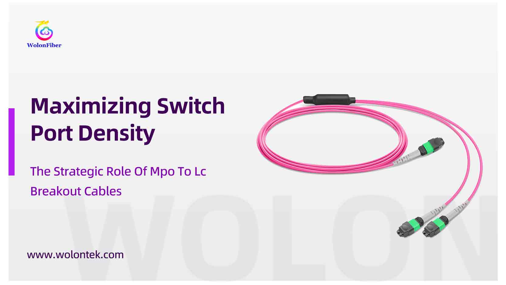
An MPO to LC breakout cable (often called a harness) takes a single high-bandwidth parallel optic port and divides it into multiple duplex discrete links.
-
100G to 4x 25G: A single QSFP28 100G transceiver (using an MPO-12 interface) is split into four separate 25G SFP28 links via LC duplex connectors.
-
400G to 4x 100G: A single 400G QSFP-DD (using an MPO-16 interface) is split into four 100G links.
The ROI Calculation: A 32-port 100G switch effectively becomes a 128-port 25G switch when utilizing breakout cables. You eliminate the need for three additional physical switch chassis, bypass the associated software licensing fees, and drastically reduce the ongoing power and cooling OPEX. The breakout cable pays for itself the moment it is plugged in.
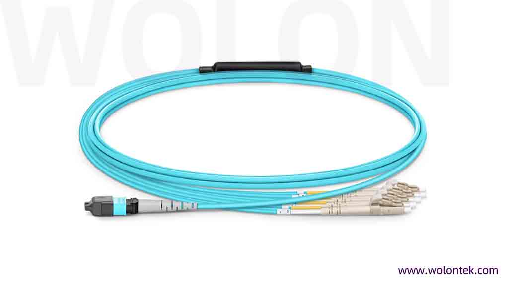
Custom OM4 MTP-8 to4x LC UPC Harness, 8-Fiber (Aqua Jacket)
Clearing the Airway: The Physics of Dense Cabling
Beyond the financial spreadsheet, breakout cables solve a severe physical engineering problem: Airflow Blockage.
If you attempt to patch 128 individual LC duplex cables from a switch down to a server rack, you create a massive “cable wall.” This dense accumulation of 2mm or 3mm PVC/LSZH jackets chokes the exhaust fans of your expensive routing hardware. When airflow drops, internal temperatures spike, causing the switch fans to draw more power, and ultimately shortening the lifespan of the ASICs.
By utilizing an MTP breakout methodology, you consolidate the bulk. A single 3mm MTP trunk runs the vertical distance of the rack, breaking out into thin, highly flexible 2mm LC legs only at the exact U-space where the server connects. You reduce the cable mass in the vertical manager by up to 75%, allowing the hot aisle to vent exactly as the mechanical engineers designed it to.

Why Specifying an “MTP” Breakout is Critical
When you split a high-speed link, you introduce connections. In optical physics, every connection point introduces Insertion Loss (IL).
If you use a cheaply manufactured, generic MPO to LC breakout cable, the ferrule misalignment can cause high insertion loss, drastically shortening your allowable link distance or causing bit-error rates (BER) on sensitive PAM4 signals.
This is why enterprise architects specify an MTP breakout. MTP® (engineered by US Conec) is a high-performance enhancement of the standard MPO connector. It utilizes a floating ferrule and elliptical guide pins to guarantee perfect physical contact. When splitting a 400G link, specifying an MTP Elite® connector ensures your insertion loss remains strictly below 0.35dB, preserving your optical budget for the rest of the network.
For a comprehensive breakdown of the mechanical differences between standard MPO and MTP®—including how polarity, gender, and ferrule design impact your optical budget—read our definitive engineering guide: [What is MTP Cable? The Ultimate Guide for Data Center Engineers].
The Engineering Details Matter: Staggered Legs
A poorly designed breakout cable is a nightmare for a data center technician. If all 8 LC legs are the exact same length, you will end up with frustrating loops of slack hanging in front of the servers.
At Wolontek, we manufacture breakout cables with the installer in mind. Leveraging the high-volume production capabilities of our Huangshi and Wutonghu facilities, we custom-engineer staggered breakout legs.
If your servers are stacked from U10 down to U13, we manufacture the LC legs in cascading lengths. This eliminates cable slack, removes the need for horizontal cable managers, and keeps the rack exceptionally clean for future maintenance.
Finalizing Your BOM (Bill of Materials)
The MPO to LC breakout cable is not just a passive accessory; it is a strategic asset that dictates how many switches you actually need to buy. By factoring port-splitting into your initial network topology, you can drastically reduce your upfront hardware CAPEX while future-proofing your spine architecture.
Ready to optimize your rack density? If you are currently evaluating the BOM for a ToR or Spine-Leaf rollout, precision manufacturing is non-negotiable. With over 400 optical technicians across our manufacturing bases, Wolontek delivers Fluke-tested, US Conec MTP breakout solutions with factory-direct pricing to scale with your project.
 Planning a Spine-Leaf Rollout?
Eliminate cable slack and airflow blockages. Get Custom MTP/MPO Breakout Cables built to your exact staggered lengths and pinout configurations.
Configure Custom MTP/MPO Cables ➤ or contact engineering for a tailored BOM.Q1: Does using a breakout cable reduce bandwidth or increase latency?
A: No. The breakout cable is purely a passive physical medium. High-speed switch ports (like a 100G QSFP28) are already transmitting parallel optical lanes (four distinct 25G lanes). The breakout cable simply separates these existing physical lanes into individual LC connectors. There is zero logical processing, meaning zero latency is added by the cable itself.
Q2: What are the most common breakout configurations in modern data centers?
A: The configuration depends on your core switch transceivers:
100G to 4x 25G: Uses an 8-fiber MPO (Base-8) to 4x LC Duplex.
40G to 4x 10G: Uses an 8-fiber MPO (Base-8) to 4x LC Duplex.
400G to 4x 100G: Uses a 16-fiber MPO (Base-16) to 4x LC Duplex.
Q3: Why should I request “staggered legs” instead of standard equal-length legs?
A: Equal-length legs create a mess of cable slack in front of your server rack, which requires horizontal cable managers and blocks airflow. Staggered legs are custom-manufactured in cascading lengths to perfectly match the U-space distance between your servers. This results in a clean, zero-slack installation that keeps the hot aisle fully ventilated.
Q4: How does insertion loss (IL) on the breakout cable affect my 400G network?
A: High-speed PAM4 signals used in 400G/800G networks are extremely sensitive to optical loss. If your breakout cable uses cheap, poorly polished MPO connectors, the high insertion loss will consume your optical budget, leading to high Bit Error Rates (BER) or complete link failure. This is why enterprise deployments strictly specify MTP® Elite connectors, ensuring the IL remains strictly below 0.35dB.
Q5: Can I mix Single-mode (OS2) breakout cables with Multimode transceivers?
A: No. The fiber type of the breakout cable must perfectly match the transceiver type. You must use OM4/OM5 breakout cables for SR4/SR8 (Short Reach) multimode transceivers, and OS2 breakout cables for DR4/DR8 (Data Center Reach) single-mode transceivers.