
Introduction
In high-density data centers, MPO (Multi-fiber Push-On) connectors are the standard for 40G, 100G, and 400G networks. However, they introduce a complexity that standard duplex LC connectors don’t have: Polarity.
Polarity ensures that the transmit signal (Tx) from one end matches the receive port (Rx) at the other. If this mapping is wrong, the link stays dark. Industry data suggests that up to 80% of MPO network issues stem from polarity or connector mismatches rather than actual cable failures.
In this guide, we break down the standard MPO polarity types, analyze real-world failure case studies, and provide quick fixes to get your network live.
Polarity mapping is arguably the most complex aspect of parallel optics. If you need to step back and understand the foundational hardware first—such as fiber counts (Base-8 vs Base-12) and MTP polish types (APC vs UPC)—start with our foundational [What is MTP Cable? The Ultimate Data Center Guide].
Part 1: The Basics – Understanding MPO Polarity Types
Before fixing errors, you must identify what you are working with. The TIA-568 standard defines three methods to handle the fiber path logic.
Method A (Straight-Through)
Structure: Key-Up to Key-Down.
Mapping: Fiber 1 goes to Fiber 1.
The Catch: Because Transceivers operate on Tx to Rx, a Type A backbone requires a “flipped” patch cord (A-to-B) on one end to correct the signal.
Best For: Simple, legacy duplex links.
Method B (Crossover / Universal)
Structure: Key-Up to Key-Up.
Mapping: Fiber 1 goes to Fiber 12.
The Catch: This creates a direct crossover.
Best For: Parallel optics (40G/100G SR4). It is often preferred because it uses standard patch cords on both ends, reducing inventory confusion.
Method C (Pairwise Flip)
Structure: Key-Up to Key-Down (Pairwise Flipped).
Mapping: Fiber 1 goes to Fiber 2; Fiber 2 goes to Fiber 1.
The Catch: Designed strictly for duplex applications.
Warning: Do not use Type C for parallel optics (40G/100G), as it will scramble the channels and fail.

Part 2: Top 4 Common MPO Polarity Mistakes
Why do MPO links fail? It usually comes down to one of these four human errors.
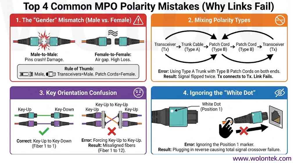
1. The “Gender” Mismatch (Male vs. Female)
MPO connectors are either Male (with guide pins) or Female (without pins).
The Error: Connecting Male-to-Male (pins crash against pins) or Female-to-Female (no alignment).
The Result: Physical damage to connector faces or high insertion loss (air gaps).
Rule of Thumb: Transceivers usually have pins (Male). Patch cords connecting to them should be unpinned (Female).
2. Mixing Polarity Types
This is the most frequent cause of outages.
The Error: Using a Type A Trunk cable with Type B patch cords on both ends.
The Result: The signal is flipped twice (or not enough), resulting in Tx connecting to Tx. The link will never come up.
3. Key Orientation Confusion
The Error: Forcing a “Key-Up to Key-Up” connection when the adapter is designed for “Key-Up to Key-Down.”
The Result: Misaligned fibers (Fiber 1 connects to Fiber 12 instead of Fiber 1).
4. Ignoring the “White Dot”
The Error: Technicians ignoring the white dot marker on the connector body, which indicates Position 1.
The Result: Plugging the connector in reverse (if the keying allows), causing total signal crossover failure.
Part 3: Real-World Case Studies
Here are two scenarios we frequently encounter in the field and how they were solved.
Case Study A: The “Legacy Upgrade” Failure
The Scenario: A data center team upgraded a 10G backbone to 40G. They kept their existing MPO trunk cables, assuming they were standard Type B. The Failure: The new 40G transceivers showed “No Link.” The Root Cause: The old trunks were actually Type A. When connected to standard Type B patch cords, the polarity was mismatched for parallel optics. The Fix: Instead of replacing the expensive trunk cables, the team replaced the patch cords on one end with Type A cords to correct the flip. Lesson: Never assume the polarity of existing cable plants. Test before you plug.
Case Study B: The “Hybrid Trunk” Disaster
The Scenario: An installer used a hybrid trunk cable (MPO to LC) for a high-density patch panel. The Failure: Half the links worked, half didn’t. The Root Cause: The trunk utilized a custom pinout not compliant with standard TIA Method B. The Fix: The team had to re-terminate the LC ends to match the correct mapping. Lesson: Avoid custom/hybrid polarities unless you have rigorous documentation. Stick to TIA standards.
Part 4: Troubleshooting & Quick Fixes
If your MPO link is down, follow this rapid response protocol.
Summary: Best Practices Checklist
To avoid expensive downtime in your next MPO deployment:
1.Standardize: Stick to Method B for all new 40G/100G/400G parallel deployments if possible. It is the most “Plug-and-Play” friendly.
2.Inspect & Clean: 80% of failures are actually dirt, not polarity. Always clean MPO end-faces before testing.
3.Labeling: Label every trunk with its Type (A, B, or C).
4.Test First: Test the trunk cable’s polarity before laying it in the tray.
MPO Polarity is Confusing. We Make It Simple.
Type A? Type B? Type C? One wrong cable can bring down your 40G/100G link.
Don’t guess. Send us your transceiver model (e.g., SR4, PLR4), and our engineers will prescribe the exact Pinout and Polarity.
Available in 8, 12, and 24 Fiber configurations (MTP/MPO).
FAQ: MPO Polarity & Installation
Q1: Can I connect a Type A cable directly to a Type B cable?
A: Generally, No. Connecting Type A to Type B directly usually results in a signal mismatch (Tx connecting to Tx). You must plan your link so that the signal transmitted from Fiber 1 eventually arrives at Fiber 12 (for parallel optics) or the correct receive pair. Always sketch the link budget and mapping before mixing cable types.
Q2: What is the difference between Male and Female MPO connectors?
A:
Male (Pinned): Has two metal guide pins sticking out. Usually found on Transceivers inside the switch.
Female (Unpinned): Has two holes. Usually found on Patch Cords and Trunk cables.
Critical Rule: Never connect Male-to-Male (pins will crash and damage the connector) or Female-to-Female (loose alignment equals high loss). Always mate Male to Female.
Q3: Which polarity type is best for 40G/100G (SR4) networks?
A: Method B (Key-Up to Key-Up) is the industry preference for parallel optics. Method B allows you to use the exact same patch cord (Type B) on both ends of the link, which simplifies inventory and reduces human error during installation.
Q4: My link is down. Is it polarity or a bad cable?
A: Statistically, it is likely Dirt or Polarity.
Clean it first: 80% of failures are due to dirty end-faces.
Check the “White Dot”: Ensure the white dot (Position 1) is aligned correctly on both ends.
Test: Use a VFL or MPO Polarity Tester to confirm light is getting through to the correct fiber position.
Q5: Can I change the polarity of an MPO connector myself?
A: Only if you are using specific Field-Changeable Connectors (like MTP PRO or PanMPO). Standard MPO connectors are factory-set. Trying to open a standard connector to flip the fibers is risky and usually voids the warranty or breaks the delicate fibers inside.