
In today’s hyperscale data centers and enterprise core networks, the physical layer is undergoing a massive transformation. As switch port densities skyrocket and bandwidth requirements migrate from 100G to 400G and 800G, traditional duplex fiber routing is no longer viable. Network architects need to maximize rack space, optimize thermal management, and establish flexible migration paths.
This is where the MPO breakout cable becomes the backbone of modern structured cabling. Whether you are deploying spine-leaf architectures or integrating AI GPU clusters, understanding the precise specifications, polarity rules, and connector types of MPO breakout assemblies is critical to ensuring zero-packet-loss connectivity.
This comprehensive guide covers everything IT professionals, contractors, and procurement managers need to know to select, deploy, and maintain MPO breakout cables efficiently.
What is an MTP/MPO Breakout Cable?
An MPO breakout cable—also widely known as an MPO fanout cable or harness cable—is a specialized fiber optic assembly designed to convert a high-density multi-fiber interface into multiple individual, lower-speed connections.
Structurally, one end of the cable is terminated with a high-density MPO (or MTP®) connector, which aggregates multiple optical fibers into a single, compact housing. The cable then passes through a breakout transition module, splitting the individual fiber strands into separate “legs.” These legs are terminated with standard duplex connectors, most commonly LC, SC, or MDC.
In modern Ethernet deployments, MPO breakout cables are the primary solution for port-breakout configurations, including:
- 40G to 10G: Connecting a single 40G QSFP+ port to four 10G SFP+ ports.
- 100G to 25G: Connecting a 100G QSFP28 port to four 25G SFP28 ports.
- 400G to 100G/50G: Splitting a 400G QSFP-DD port into four 100G or eight 50G optical links.
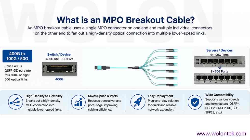
Unlike traditional patching, which requires running individual cables for every server, MPO breakout assemblies consolidate the trunk routing, significantly reducing cable bulk while supporting seamless integration between different Ethernet generations.
The Mechanics: How MTP/MPO Breakout Cables Work
MPO breakout cables operate on the principle of parallel optical transmission. Instead of sending data over a single pair of fibers (Tx/Rx) using multiple wavelengths (like WDM), parallel optics split the data stream across multiple separate physical fibers simultaneously.
Let’s look at a practical example: a 100GBASE-SR4 optical transceiver.
- The module transmits 100Gbps by breaking the signal into four separate 25Gbps lanes.
- It uses 4 transmit fibers (Tx) and 4 receive fibers (Rx), totaling 8 active fibers.
- The MPO breakout cable takes these 8 fibers from the single switch port and physically routes each Tx/Rx pair to four independent 25GBASE-SR transceivers on the server side.
| High-Speed Transceiver (Spine / Core Switch) |
Interface Type | Breakout Configuration (Leaf / Edge Server) |
Recommended Infrastructure Cable |
|---|---|---|---|
| 40GBASE-SR4 | QSFP+ | 4 × 10G SFP+ | Base-8 MPO to 4x LC Duplex (OM4) |
| 100GBASE-SR4 | QSFP28 | 4 × 25G SFP28 | Base-8 MPO to 4x LC Duplex (OM4 Elite) |
| 200GBASE-SR4 | QSFP56 | 4 × 50G SFP56 | Base-8 MPO to 4x LC Duplex (OM4 Premium) |
| 400GBASE-SR8 | QSFP-DD / OSFP | 8 × 50G SFP56 | Base-16 MPO to 8x LC Duplex (OM5) |
| 400GBASE-DR4 | QSFP-DD | 4 × 100G DR (Singlemode) | Base-8 Single-Mode MPO to 4x LC Duplex (OS2) |
Architectural Note: If your upcoming infrastructure overhaul is driven heavily by 400G PAM4 signaling or port bifurcation on spine-leaf switches, you will need to adhere to much tighter insertion loss thresholds. Review our structural optimization blueprint: MPO to LC Breakout Cables: The 400G Data Center Wiring Guide.
Accelerating Your 100G/400G Network Migration?
Eliminate lead-time stress and attenuation risks. Get factory-terminated, ultra-low-loss MPO/MTP® breakout cables built exactly to your architectural blueprint.
MPO vs MTP® Connectors: Understanding the Difference
In procurement documents, “MPO” and “MTP” are often used interchangeably, but they are not identical.
- MPO (Multi-Fiber Push-On): This is the generic, industry-standardized connector type defined by international regulatory bodies (IEC-61754-7 and TIA-604-5). Any manufacturer can produce an MPO connector as long as it meets these baseline dimensions.
- MTP® (Mechanical Transfer Push-On): This is a registered trademark and a proprietary, high-performance iteration of the MPO connector engineered by US Conec. It features multiple mechanical enhancements designed to lower insertion loss and increase durability.
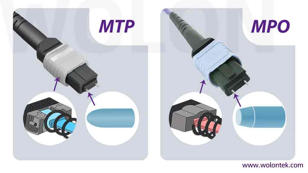
| Technical Feature | Standard MPO Connector | Premium MTP® Connector (US Conec) |
|---|---|---|
| Standardization | Baseline IEC-61754-7 & TIA-604-5 standards. | Exceeds Global Criteria with rigorous mechanical/optical benchmarks. |
| Ferrule Design | Fixed molded ferrule; prone to spring-fatigue displacement. | Floating Ferrule: Ensures continuous physical contact under structural load. |
| Alignment Pins | Standard cylindrical pins; high friction on guide holes. | Elliptical Guide Pins: Drastically reduces friction and wear during mating cycles. |
| Spring Architecture | Basic cylindrical spring; minimal rib-rib clearance. | Optimized Spring Geometry: Eliminates fiber damage during high-pressure installation. |
| Best Applied To | Legacy LAN environments and basic low-speed patching. | Hyperscale Data Centers, AI Clusters & Strict IL Budgets. |
💡 Procurement Insight: Balancing the premium cost of Tier-1 optical components against a tight project budget is a common hurdle for infrastructure managers. To understand how to optimize your capital expenditure without risking link attenuation, read our commercial evaluation: Sourcing MPO Cable: China Factory vs USA Distributor (A Cost & Quality Analysis).
Decoding MPO Fiber Counts: Which Base Architecture is Right?
As networks evolve, selecting the correct fiber count (Base architecture) determines your network’s efficiency and future scalability.
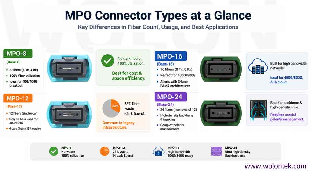
MPO-8 (Base-8 Routing)
MPO-8 is the undisputed champion for modern parallel optics. It features 8 fibers (4 Tx, 4 Rx). Because standard QSFP transceivers (40G/100G) only require 8 fibers, using Base-8 assemblies guarantees 100% fiber utilization. There are no wasted, “dark” fibers. It is the most cost-effective and space-efficient choice for 40G-to-10G and 100G-to-25G breakout applications.
MPO-12 (Base-12 Routing)
Historically, MPO-12 was the original industry standard. It features 12 fibers in a single row. However, when used for 40G/100G SR4 transceivers, only the outer 8 fibers transmit data, leaving the middle 4 fibers completely unused. While heavily deployed in legacy structured cabling, Base-12 is generally avoided in new parallel optic designs due to this 33% fiber waste.
MPO-16 (Base-16 Routing)
Driven by the massive bandwidth demands of 400G and 800G, MPO-16 provides a single row of 16 fibers (8 Tx, 8 Rx). It perfectly aligns with the 8-lane PAM4 networking architectures required by 400GBASE-SR8 transceivers. MPO-16 is rapidly becoming the standard for AI/GPU clusters and next-generation cloud infrastructure.
MPO-24 (Base-24 Routing)
MPO-24 utilizes two rows of 12 fibers. It is primarily deployed in backbone trunk cabling, high-density aggregation panels, and cross-connects. While it offers unparalleled spatial density, it significantly complicates polarity management and requires extreme precision during installation.
Core Benefits of Deploying MPO Breakout Cables
Why are data centers completely abandoning traditional patching in favor of MPO fanout assemblies?
- Unmatched High-Density Connectivity: A single MPO-24 cable can replace 12 individual duplex LC cables. This drastically reduces the physical footprint in cable trays and rack managers, allowing facilities to maximize switch port density. For a comprehensive review of vetted optical brands specializing in these high-density rack elevations, see our market analysis of the Top 5 MPO To LC Breakout Cable Manufacturers For Server Connections.
- Superior Cable Management & Airflow: Legacy cabling creates “spaghetti” congestion that blocks cooling fans, leading to thermal throttling. MPO breakouts streamline routing, ensuring optimal airflow and reducing cooling costs.
- Plug-and-Play Rapid Deployment: Factory-terminated and pre-tested MPO cables eliminate the need for slow, error-prone field splicing. Rack installation times are reduced from days to mere hours.
- Flexible, Phased Migration Paths: Breakout cables allow for incremental upgrades. You can install a new 400G core switch today and break it out to your existing 100G servers, avoiding the massive capital expenditure of a “rip-and-replace” upgrade.
Engineering Checklist: MPO Breakout Cable Selection Considerations
Selecting an MPO breakout cable requires matching precise specifications to your active equipment. A single mismatch will prevent link establishment. To avoid expensive ordering errors, ensure you cross-reference your bill of materials with our tactical engineering guide on Specifying MTP/MPO Breakout Cables: Configurations and Hardware Pitfalls.
1. Fiber Type (Multimode vs Singlemode)
- Multimode (OM3 / OM4 / OM5): Ideal for short-reach connections within the same data hall (e.g., Spine-to-Leaf, Top-of-Rack). Identifiable by their Aqua (OM3/OM4) or Lime Green (OM5) jackets.
- Singlemode (OS2): Essential for long-distance data center interconnects (DCI), campus networks, or Silicon Photonics transceivers (like 100G PSM4 or 400G DR4). Identifiable by their Yellow jackets.
2. Polarity Management (The Critical Factor)
Polarity ensures that the transmit (Tx) laser points directly into the receive (Rx) photodiode.
- Type A (Straight-Through): Fiber 1 maps to Fiber 1. Requires a flipped patch cord at one end.
- Type B (Reversed / Cross-Connect): Fiber 1 maps to Fiber 12. Type B is the most widely adopted standard for MPO breakout cables in parallel optics, ensuring seamless Tx-to-Rx mating.
- Type C (Pair Flipped): Primarily used for duplex traffic routing; rarely used for high-speed breakout.
3. Gender / Pin Configuration (Male vs Female)
MPO connectors are either Male (with guide pins) or Female (without guide pins).
- Rule of Thumb: All optical transceivers (QSFP, QSFP-DD) have built-in pins. Therefore, the MPO breakout cable plugging directly into the transceiver MUST BE FEMALE. Plugging a pinned cable into a pinned transceiver will shatter the optical lens.
4. Insertion Loss (IL) Budgets
As network speeds increase, the tolerance for signal loss drops drastically. A 400G link cannot survive the loss budgets acceptable in 10G networks. Always specify Elite/Low-Loss MPO connectors (typically ≤0.35dB max, optimally ≤0.20dB) for high-speed breakouts.
Stop Fighting Transceiver Failures & Packet Loss
Confused by Type A/B/C polarity alignment? Tighter optical power budget than expected? Our veteran fiber engineering team in China Optics Valley is here to help synchronize your specifications.
Best Practices for Installation and Maintenance
Even the highest-quality MPO cables will fail if handled improperly. MPO assemblies are precision optical instruments.
- Handle with Extreme Care: Never pull an MPO cable by the connector housing. Use the pulling eye. Avoid twisting or crushing the breakout transition module.
- Respect the Bend Radius: Tight bends cause macro-bending loss. The bend radius must never be less than 10 times the cable’s outer diameter during operation, and 15 times during installation routing.
- Inspect Before You Connect (IBYC): Because an MPO connector holds 8 to 24 fibers in a microscopic area, a single speck of dust can take down multiple lanes. Always use a specialized MPO digital microscope and one-click MPO cleaners before mating, even if the cable is fresh from the bag.
- Perform OTDR / IL Testing: Post-installation, validate the link health using optical loss test sets (OLTS) to ensure the insertion loss remains within your transceiver’s optical budget.
The Future of MPO Breakout Connectivity
The demand for parallel optical transmission is far from peaking. As hyperscalers rapidly adopt 800G (using 8x100G lanes) and prepare for 1.6T Ethernet, the physical infrastructure relies entirely on advanced MPO and MTP connectivity.
Emerging architectures, such as AI-optimized optical fabrics, 224G SerDes technologies, and Co-Packaged Optics (CPO), will drive the industry toward ultra-high-density MPO-16 and specialized multifiber interconnects. Committing to a robust, scalable MPO cabling strategy today is the only way to ensure your physical layer survives the bandwidth demands of tomorrow.
Conclusion
MPO breakout cables are not just a cabling accessory; they are a strategic architectural decision. By efficiently fanning out high-density optical interfaces into manageable, lower-speed links, they resolve the spatial constraints of modern data centers while providing a cost-effective, phased migration path.
Whether you are configuring an enterprise core network or building out a liquid-cooled AI cluster, mastering MPO architectures—specifically Base-8 efficiencies, Type B polarity, and ultra-low-loss MTP connectors—will guarantee a resilient, high-performance optical infrastructure for generations of hardware to come.
What exactly does an MPO breakout cable do in a data center?
An MPO breakout cable (or fanout cable) converts a single high-speed, multi-fiber port (like a 100G QSFP28 transceiver) into multiple individual duplex ports (like four 25G SFP28 transceivers). It acts as a physical optical splitter, allowing high-density core switches to communicate with multiple lower-speed servers without using intermediate patch panels.
Should I buy a Base-8 or Base-12 MPO breakout cable for a 100G SR4 network?
You should strictly use Base-8. A 100GBASE-SR4 transceiver only utilizes 8 fibers (4 to transmit, 4 to receive). If you use a Base-12 cable, the middle 4 fibers are completely blind and unused. Base-8 ensures 100% fiber utilization, reducing cost and cable diameter.
What is the difference between Type A and Type B polarity in breakout cables?
Type B is the standard for parallel optics and breakout applications. It uses a reversed internal fiber mapping (Fiber 1 to Fiber 12), ensuring that the Transmit lasers on the spine switch align perfectly with the Receive photodiodes on the edge servers. Type A uses straight-through mapping and requires complex patching workarounds to fix the Tx/Rx alignment.
Can I plug a Male MPO cable into my switch transceiver?
No. Switch transceivers (QSFP, OSFP, QSFP-DD) are manufactured with integrated alignment pins inside the port. To mate properly without causing severe physical damage, any cable plugging directly into the transceiver must be a Female (unpinned) connector. Male connectors are used strictly for mating cables together behind patch panels.
Why are some MPO cables Aqua and others Yellow or Lime Green?
Cable jacket colors follow standard optical coding to prevent catastrophic installation errors.
Aqua: OM3 or OM4 Multimode (for short-reach 10G/40G/100G).
Lime Green: OM5 Wideband Multimode (optimized for SWDM).
Yellow: OS2 Single-mode (for long-reach links, DR4, or PSM4 transceivers).
Does using a breakout cable increase data latency?
No. An MPO breakout cable is a 100% passive optical component. Light travels through the breakout transition module without any processing, switching, or electronic conversion. It introduces zero latency to your network; the only minor variable is the minimal insertion loss (dB) caused by the physical connection points.
Can I use MPO breakout cables for Single-mode applications like 400G-DR4?
Absolutely. 400GBASE-DR4 transceivers rely on parallel Single-mode technology. An OS2 Single-mode MPO breakout cable (usually 8-fiber) can split a 400G DR4 port into four individual 100GBASE-DR connections, allowing long-distance connections (up to 500m or 2km) to leaf switches.
What fire safety rating is required for these cables?
Fire ratings depend on your facility’s local building codes. LSZH (Low Smoke Zero Halogen) is standard in Europe and highly recommended globally for data center racks, as it emits no toxic gas when burned. In North America, strict codes often mandate OFNP (Optical Fiber Nonconductive Plenum) for cables run through air-handling spaces.