

In modern leaf-spine data center topologies, maximizing switch faceplate density is a strict operational mandate. As core and spine switches migrate to 100G, 400G, and 800G ASICs, high-density transceiver form factors (QSFP28, QSFP-DD, OSFP) have become the standard.
However, edge devices, legacy servers, and storage arrays often still operate on 10G, 25G, or 100G duplex LC interfaces. To bridge this bandwidth gap without wasting expensive switch ports, network architects rely on port bifurcation using MPO to LC breakout cables (also known as fanout cables).
This guide details the engineering rules for deploying MPO to LC breakout assemblies, focusing on Base-8 architecture, strict insertion loss (IL) budgets, and precise Tx/Rx polarity mapping.
While Base-8 is strictly required for 400G DR4/SR8 transceivers, you can review how it compares to legacy Base-12 and next-gen Base-16 deployments in our comprehensive [MPO Breakout Cable Architecture Guide].
1. The Physics of Port Bifurcation
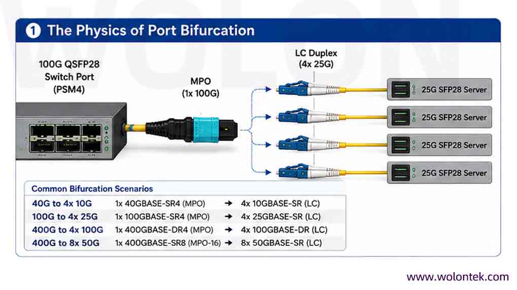
Port bifurcation is the process of dividing a single high-speed parallel optic transceiver port into multiple lower-speed duplex channels. The MPO to LC breakout cable serves as the physical layer enabler for this logical split.
For instance, a single 100G QSFP28 switch port running the PSM4 protocol transmits data over 4 parallel lanes of 25G. By deploying an MPO to LC breakout cable, that single 100G port is physically split to connect four separate 25G SFP28 servers.
Common Bifurcation Scenarios:
40G to 4x 10G: 1x 40GBASE-SR4 (MPO) ➔ 4x 10GBASE-SR (LC)
100G to 4x 25G: 1x 100GBASE-SR4 (MPO) ➔ 4x 25GBASE-SR (LC)
400G to 4x 100G: 1x 400GBASE-DR4 (MPO) ➔ 4x 100GBASE-DR (LC)
400G to 8x 50G: 1x 400GBASE-SR8 (MPO-16) ➔ 8x 50GBASE-SR (LC)
2. The Base-8 vs. Base-12 Architecture Dilemma
The most critical decision when specifying MPO to LC breakout cables is selecting the correct fiber array baseline. While 12-fiber (Base-12) MPO connectors were the legacy standard, Base-8 architecture is the undisputed requirement for modern parallel optic transceivers.
A standard QSFP SR4/DR4 Transceiver utilizes exactly 8 fibers (4 Transmit and 4 Receive) to deliver 4 lanes of traffic. If a Base-12 MPO Breakout Cable is plugged into this transceiver, the outer 8 fibers will carry the signal, but the middle 4 fibers remain completely dark (unused). This results in a 33% waste of optical glass and introduces severe routing complexities in high-density patch panels.
By specifying a Base-8 MPO to LC breakout cable (which terminates 8 fibers into 4 duplex LC uniboot connectors), infrastructure managers ensure 100% fiber utilization and seamless Tx/Rx mapping.

Technical Comparison: Base-8 vs. Base-12 MPO Breakouts
| Specification | Base-8 MPO Breakout | Base-12 MPO Breakout |
|---|---|---|
| Fiber Utilization (SR4/DR4) | 100% (8 of 8 fibers used) | 66% (Middle 4 fibers are dark) |
| Typical Transceiver Match | QSFP+, QSFP28, QSFP-DD | Legacy 10G/40G backbones |
| Cable Bulk / Density | Streamlined, minimal trunk OD | Unnecessary weight and bulk |
| Cost Efficiency per Port | High (No wasted optical glass) | Low (Paying for unused glass) |
| Network Migration Path | Seamless scaling to 400G/800G | Requires conversion cassettes |
Standardize your racks with Wolontek’s exact-length Base-8 MPO to LC breakout cables. Engineered with genuine US Conec MTP® Elite connectors and ultra-low loss LC uniboots for flawless 400G port bifurcation.
Request a Custom Configuration & Factory Quote3. Engineering Strict Insertion Loss (IL) Budgets
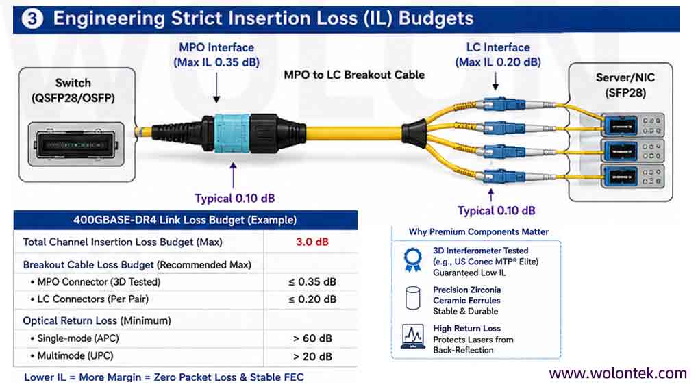
As networks upgrade to 400G PAM4 signaling, the allowable optical link loss drops drastically. A standard 400GBASE-DR4 transceiver has a maximum channel insertion loss budget of just 3.0 dB .
In an MPO to LC breakout scenario, the total loss is dictated by the quality of the MT ferrule (MPO side) and the ceramic ferrules (LC side). Relying on generic, mass-produced MPO connectors often introduces >0.75 dB of loss at the switch interface alone, crippling the link before it even reaches the server.
To guarantee zero packet loss and FEC (Forward Error Correction) margin stability, breakout cables must be specified with Premium/Elite-grade components :
MPO Interface: Must be terminated with 3D-interferometer tested ferrules (e.g., US Conec MTP® Elite) guaranteeing a maximum IL of 0.35 dB (0.10 dB typical).
LC Interface: Must utilize precision zirconia ceramic ferrules with a maximum IL of 0.20 dB .
Return Loss (RL): Minimum >60 dB for Single-mode (APC polish) and >20 dB for Multimode (UPC polish) to prevent back-reflection damage to transceiver lasers.
Relying on generic, mass-produced MPO connectors often introduces >0.75 dB of loss at the switch interface alone, crippling the link before it even reaches the server. Deciding whether the premium ferrule is worth the investment is critical; our [MTP vs MPO cost analysis and price guide] details exactly when to upgrade based on your link loss budget.
4. Polarity and Gender Rules for Transceiver Breakouts
Failure to properly match connector gender and polarity is the leading cause of deployment delays when wiring MPO to LC links.
The Gender Rule (Pin/No-Pin)
Parallel optic transceivers (QSFP, OSFP) are universally manufactured with Male (Pinned) MPO interfaces. Therefore, the MPO connector on your breakout cable plugging directly into the switch port must be Female (Unpinned). Attempting to force a pinned cable into a pinned transceiver will permanently shatter the optical lenses inside the module.
Rx to Tx Mapping (Polarity)
For an MPO to LC breakout cable to function, the transmission (Tx) lane from the switch must correctly route to the receiving (Rx) port on the server’s network interface card (NIC), and vice versa.
A standard breakout cable utilizes Type B (Cross-Over) internal routing.
The 8 fibers are crossed sequentially so that Lane 1 (Tx) on the MPO connector successfully lands on the corresponding Rx side of the first LC duplex pair.
Clear leg-labeling (Leg 1 through 4) is mandatory. The LC legs must be labeled at the factory to correspond with the switch port lane assignments, eliminating guesswork during server deployment.
The 8 fibers are crossed sequentially so that Lane 1 (Tx) on the MPO connector successfully lands on the corresponding Rx side of the first LC duplex pair. Because transceiver mapping is the most common point of failure, we highly recommend consulting our comprehensive [MPO polarity guide covering common mistakes and fixes] before deploying your trunks.
5. Physical Cable Management: Staggering and Armor
High-density top-of-rack (ToR) and end-of-row (EoR) deployments require more than just optical performance; they demand mechanical flexibility.
Custom Staggering: When breaking out a 100G switch port to a 1RU server block, the LC legs should not be cut to identical lengths. Specifying a custom “stagger” (e.g., 5cm increments between LC legs) prevents cable slack buildup and maximizes airflow around hot server exhausts.
Uniboot LC Connectors: Ensure the LC end utilizes a uniboot design (two fibers housed in a single 2.0mm or 3.0mm jacket) with a push-pull tab. This cuts the physical cable bulk by 50% and allows technicians to extract the LC connector from a densely packed server NIC without disrupting adjacent links.

High-density top-of-rack (ToR) and end-of-row (EoR) deployments require more than just optical performance; they demand mechanical flexibility. Routing these breakout assemblies cleanly often requires robust chassis hardware—see our ranking of the [top China MPO fiber patch panel suppliers] to ensure your physical enclosures match your optical performance.
Conclusion: Securing the Physical Layer
Specifying an MPO to LC breakout cable is an exact science. Network architects must dictate the exact fiber count (Base-8), guarantee the MT ferrule quality (Max 0.35dB IL), and enforce strict gender matching (Unpinned to Transceiver). By adhering to these physical layer rules, data centers can safely bifurcate expensive 400G switch ports while maintaining the precise Tx/Rx mapping required for modern server architectures.
Upgrade Your Infrastructure, Not Your Budget. Stop paying Tier-1 brand markups for generic breakout cables.
WolonFiber engineers and manufactures 100% 3D-tested, CPR-compliant MPO to LC assemblies directly from Optical Valley. Whether you need OM4 Base-8 fanouts or OS2 OSFP breakouts, we deliver custom lengths and staggers globally in 7-10 days.
Can I use a legacy Base-12 MPO breakout cable for a 100G or 400G QSFP transceiver?
Technically, yes, but it is highly discouraged. QSFP (SR4/DR4) transceivers only utilize 8 fibers to transmit 4 lanes of traffic. If you plug a Base-12 MPO connector into a Base-8 transceiver, the middle 4 fibers will remain completely dark (unused). This wastes optical glass, increases cable diameter, and unnecessarily complicates patch panel routing. Always specify Base-8 MPO to LC breakout cables for modern parallel optics.
What is the correct gender (Pinned vs. Unpinned) for my MPO breakout cable?
You must specify Unpinned (Female) MPO connectors. Almost all high-speed parallel optic transceivers (QSFP+, QSFP28, OSFP) are manufactured with Pinned (Male) interfaces built into the module. Attempting to force a Pinned cable into a Pinned transceiver will instantly shatter the alignment pins and destroy the optical lenses.
What is the maximum allowable insertion loss (IL) for a 400G breakout cable?
Under IEEE 802.3bs standards, a 400GBASE-DR4 link has a strict total channel insertion loss budget of just 3.0 dB. To leave enough optical margin for trunk cables and patch panels, your MPO to LC breakout assembly should contribute no more than 0.50 dB total (max 0.35 dB at the MPO interface and max 0.15 dB at the LC uniboot interface). This is why specifying premium components like US Conec MTP® Elite ferrules is critical.
How do MPO to LC breakout cables handle Tx/Rx polarity?
To ensure the signal transmits correctly from the switch to the server, breakout cables are manufactured with internal Type B (crossover) routing. This physical crossover guarantees that the Transmit (Tx) lanes exiting the switch’s MPO port land precisely on the Receive (Rx) fibers of the duplex LC ends at the server NIC.
Why do you recommend “staggered” LC legs instead of equal lengths?
Equal-length LC legs create massive cable slack when plugging into vertically stacked servers in a rack. This slack blocks server exhaust vents and severely reduces rack cooling efficiency. By specifying a custom stagger (e.g., LC legs increasing in length by 2 inches sequentially), the cable routes cleanly down the server stack without excess looping, optimizing airflow.