
By the WolonFiber Engineering Team | Data Center Infrastructure & Optical Sourcing
As data centers migrate to 40G, 100G, and 400G Ethernet, high-density fiber physical layers are no longer optional—they are mandatory. At the heart of this migration is the MPO (Multi-fiber Push-On) connector.
However, specifying MPO cabling is notoriously complex. A single mismatch in polarity, gender, or end-face geometry can result in network downtime or permanently damaged Transceiver modules. This guide breaks down the engineering specifications of MPO connectors, the critical difference between MPO and MTP®, and how to correctly manage A/B/C polarity.
1. MPO vs MTP® Connectors: What is the Difference?
While “MPO” is the generic industry term defined by IEC 61754-7 and TIA/EIA 604-5, MTP® is a registered trademark of US Conec.
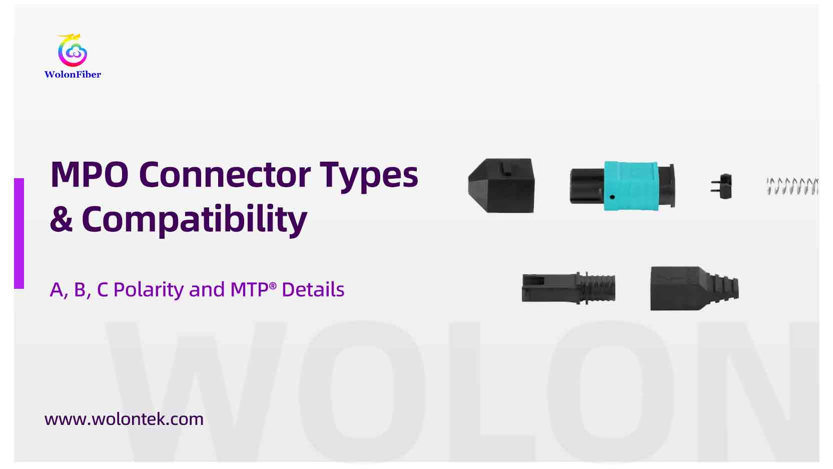
An MTP® connector is an advanced, high-performance MPO connector engineered with proprietary improvements to ensure lower insertion loss and higher mechanical durability:
-
Floating Ferrule Technology: The MTP® ferrule floats inside the housing, maintaining stable physical Contact between mated fibers even when the cable is under strain.
-
Elliptical Guide Pins: Unlike standard cylindrical pins in generic MPOs, MTP® uses stainless steel elliptical tips. This drastically reduces wear and debris generation inside the guide holes over 500+ mating cycles.
-
Thermal Stability: MTP® ferrules are molded from PPS (polyphenylene sulfide) glass-filled polymer, ensuring the ferrule resists thermal expansion in high-temperature data center aisles.
Engineering Rule of Thumb: All MTP® connectors are MPO connectors, but not all MPO connectors are MTP®. For critical 100G/400G spine-and-leaf links, specifying genuine MTP® components is highly recommended to guarantee a maximum Insertion Loss (IL) of 0.35dB.
2. Managing MPO Polarity: Type A, B, and C
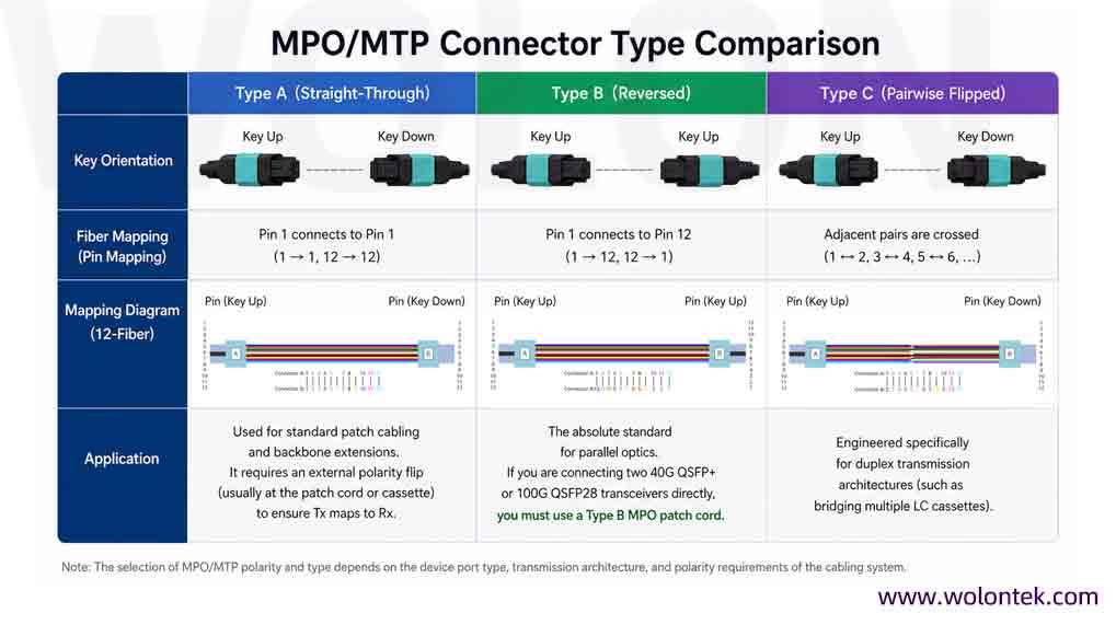
Polarity defines the mapping of optical signals from the Transmitter (Tx) to the Receiver (Rx). In multi-fiber cables, reversing a single channel can take down the entire link. TIA-568 standards define three primary polarity methods:
MPO Polarity-Type A (Straight-Through)
-
Key Orientation: Key Up to Key Down.
-
Fiber Mapping: Pin 1 connects to Pin 1 (1→1, 12→12).
-
Application: Used for standard patch cabling and backbone extensions. It requires an external polarity flip (usually at the patch cord or cassette) to ensure Tx maps to Rx.
MPO Polarity-Type B (Reversed)
-
Key Orientation: Key Up to Key Up.
-
Fiber Mapping: Pin 1 connects to Pin 12 (1→12, 12→1).
-
Application: The absolute standard for parallel optics. If you are connecting two 40G Qsfp+ or 100G QSFP28 transceivers directly, you must use a Type B MPO patch cord.
MPO Polarity-Type C (Pairwise Flipped)
-
Key Orientation: Key Up to Key Down.
-
Fiber Mapping: Adjacent pairs are crossed (1↔2, 3↔4).
-
Application: Engineered specifically for duplex transmission architectures (like bridging multiple LC cassettes).
Want to learn more about MPO polarity? Check out our guide: MPO Polarity Guide: Common Errors, Case Studies, and Quick Fixes.
3. Connector Gender and Mating Rules (Crucial)
Unlike LC or SC connectors, MPO connectors rely on an asymmetrical mating system to ensure the microscopic fiber cores align perfectly.
Male (Pinned): Contains two stainless steel guide pins protruding from the ferrule.
Female (Unpinned): Contains two precision guide holes.
The Golden Rules of MPO Mating:
1.Always mate Male to Female.
2.Never mate Male to Male: The guide pins will crash into each other, instantly crushing the ferrules and destroying both cables.
3.Never mate Female to Female: Without pins to align the MT ferrule, the fiber cores will not align, creating a massive air gap and critical insertion loss.
4.Transceiver Reality Check: Almost all high-speed transceivers (QSFP, OSFP) are equipped with Male (Pinned) MPO interfaces. Therefore, the MPO patch cord plugging into the switch must be Female (Unpinned).
4. Fiber Count and Color Coding Standards
You cannot plug a 12-fiber MPO into a 24-fiber MPO. The footprint is identical, but the internal core mapping will fail. Ensure strict adherence to color coding to prevent deployment errors:
|
Fiber Type |
Jacket & Connector Boot Color |
Typical Application |
|
OS2 (Single-mode) |
Yellow (Green APC connector) |
Long-haul, DCI, >500m reaches |
|
OM3/OM4 (Multimode) |
Aqua / Erika Violet |
10G/40G/100G short-reach (up to 150m) |
|
OM5 (Multimode) |
Lime Green |
SWDM4 applications |
Note: Single-mode MPO/MTP connectors are almost universally manufactured with an 8° Angled Physical Contact (APC) polish to minimize back-reflection (Return Loss >60dB). Multimode connectors typically use a Flat (UPC) polish.
5. 3D Interferometer Testing: The Ultimate Reliability Metric
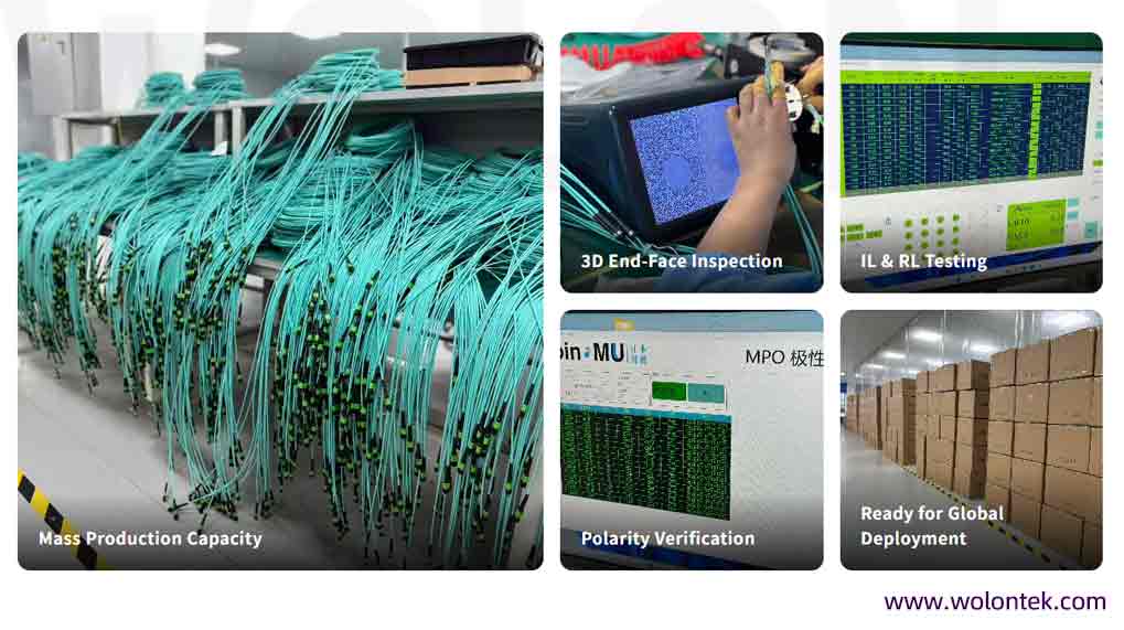
A high-quality MPO connection cannot be verified by the naked eye. Before accepting bulk cabling from an OEM supplier, insist on seeing the 3D Interferometer end-face geometry reports.
To meet IEC PAS 61755-3-31 standards, the factory must strictly control three geometric parameters:
1.Fiber Height: Ensures proper physical contact. If fibers are too low, air gaps cause high insertion loss; if too high, mating forces will crack the glass.
2.Radius of Curvature: Optimizes the mating pressure across the entire MT ferrule.
3.Coplanarity: Ensures all 12 or 24 fibers are polished to the exact same relative height. A single recessed fiber in an MPO array can kill a 400G link.
Summary: The Procurement Checklist
When specifying MPO/MTP patch cords, cassettes, or trunks for your next data center upgrade, clearly define the following parameters to your supplier:
1.Connector Grade: Generic MPO vs Genuine US Conec MTP® Elite.
2.Fiber Count: 8, 12, 16, or 24 cores.
3.Fiber Mode: OS2 (APC), OM4, or OM5.
4.Gender: Male (Pinned) or Female (Unpinned).
5.Polarity: Type A, B, or C.
6.Fire Rating: LSZH, OFNP (Plenum), or OFNR (Riser).
🚀 Ready to Optimize Your Fiber Optic Infrastructure?
Don’t let high brand markups and bottlenecked supply chains stall your data center expansion. Whether you are architecting a new 400G spine-and-leaf cluster or retrofitting an existing enterprise network, getting the physical layer right is the first step toward long-term reliability.
Why WolonFiber is the strategic choice for your 2026 projects:
-
BOM Cost Efficiency: Bypass the distribution layers and partner directly with an ISO-certified manufacturing hub.
-
Hard Engineering Data: We provide full 3D Interferometer test reports and DoP (Declaration of Performance) certifications for every batch, ensuring you get Tier-1 optical performance without the premium logo markup.
-
Rapid Deployment: From custom polarity configurations to specialized breakout lengths, we manufacture and ship your custom cabling in days, not months.
Stop guessing your optical compatibility. Submit your project’s Bill of Materials (BOM) to our engineering team today for an instant performance-matched quote and a verified factory lead-time delivery schedule.
👉 [CTA Button: Get My Factory-Direct Quote & Technical BOM Match]