
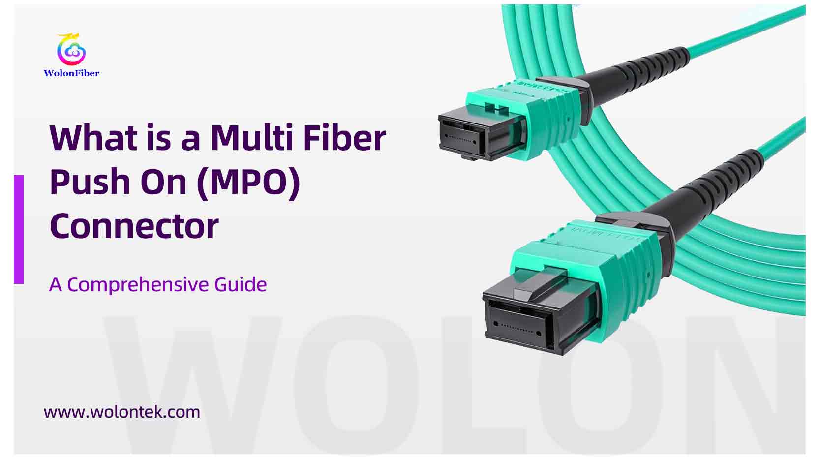
A Multi-fiber Push-On — commonly shortened to MPO — is a type of fiber optic connector that joins many optical fibers at once using a single rectangular ferrule and a push-in motion. In plain terms: where a typical LC or SC Connector handles one fiber at a time, an MPO connector handles multiple fibers together — often 8, 12, 24 or more — so you can move dozens of channels with a single click. This single idea — multi channel mating in one movement — is why multi fiber push on connectors are the backbone of modern data center connectivity and high-density fiber termination strategies.
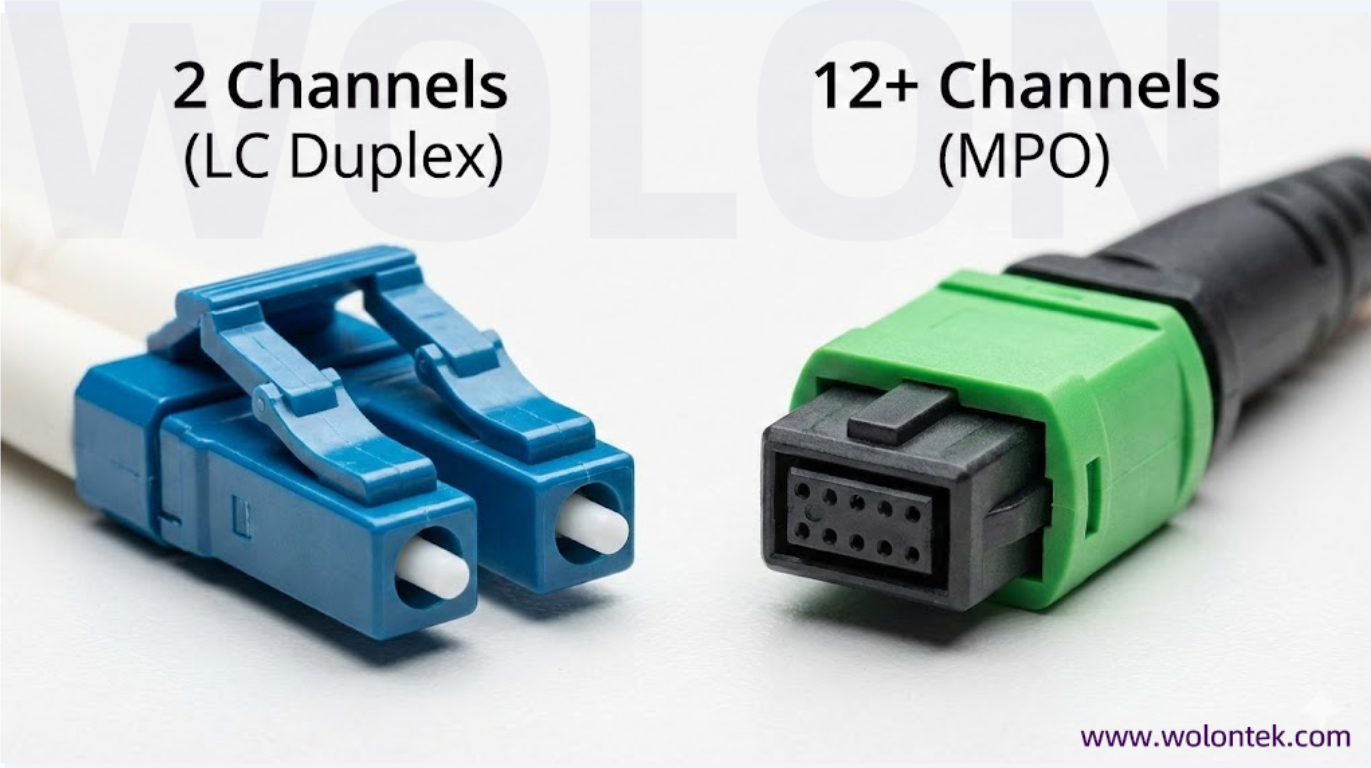
Clear definition — what “Multi Fiber Push On” (MPO) actually means
When you say Multi-Fiber Push-On, you’re naming the behavior and the design in one breath: multi-fiber because the ferrule contains many fiber endfaces laid out in a row or array; push-on because you mate it by pushing the connector into its socket where guide pins and a keyed housing ensure alignment. The MPO connector is therefore a multi-channel termination point — a compact, repeatable method to connect many fibers simultaneously. If you need to aggregate several fiber channels into one physical port — for trunking or parallel optics — the multi fiber push on concept is exactly what you want.
What MPO connector consists of?
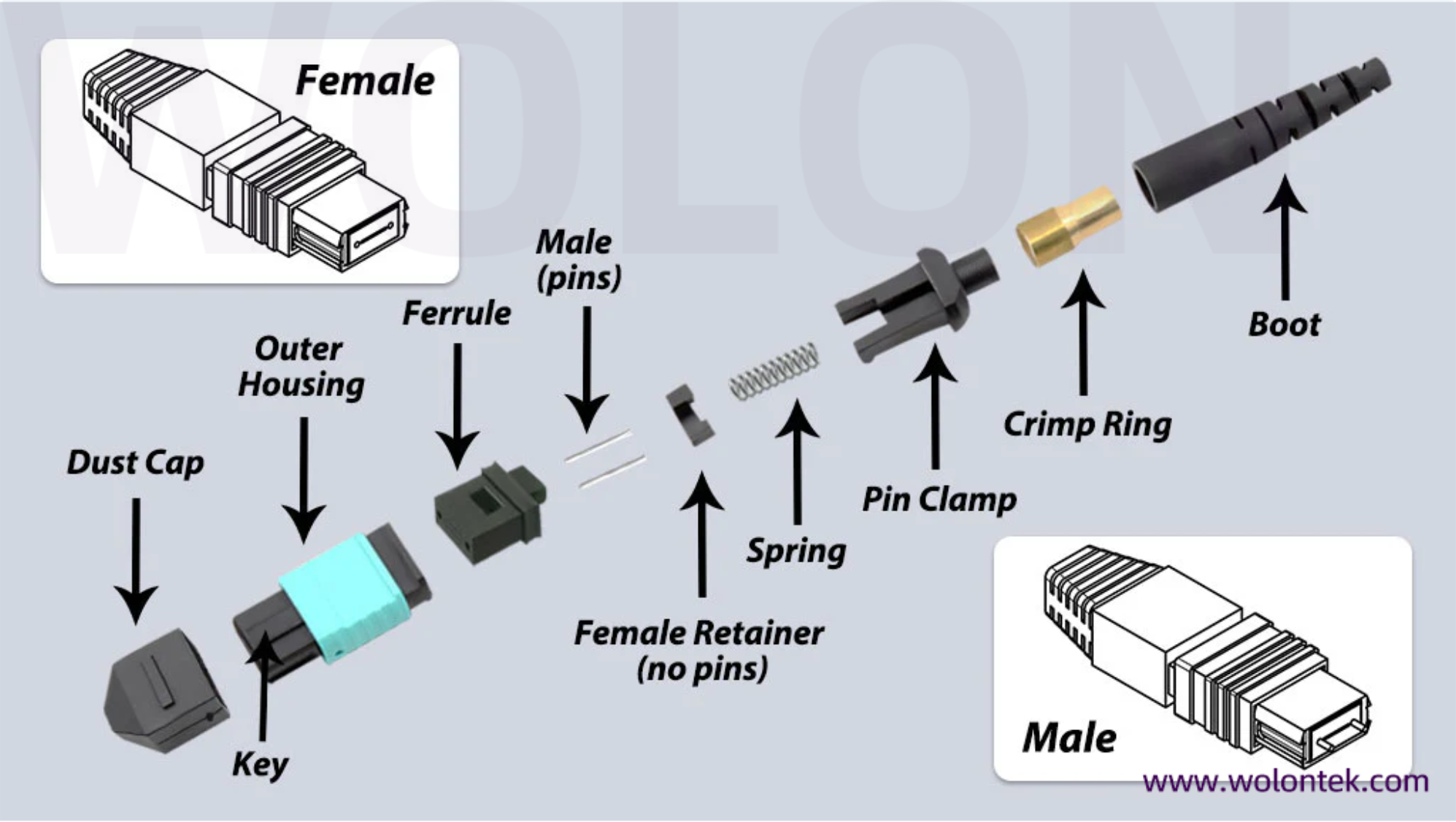
An MPO connector consists of:
-
a rectangular ferrule holding multiple fiber endfaces,
-
alignment pins (male) or holes (female) to guarantee precise mating,
-
a plastic housing with a key that enforces rotation and polarity, and
-
a latch or clip to keep it secure.
In procurement you will see “MPO” and trademarked MTP® used interchangeably; both describe multi-fiber push on-style connectors, but MTP® signals a specific vendor’s higher-tolerance variant. Be explicit in orders: request MPO connector or MTP® only as your design requires.
Why data centers adopt MPO connectors — the practical case for multi fiber push on
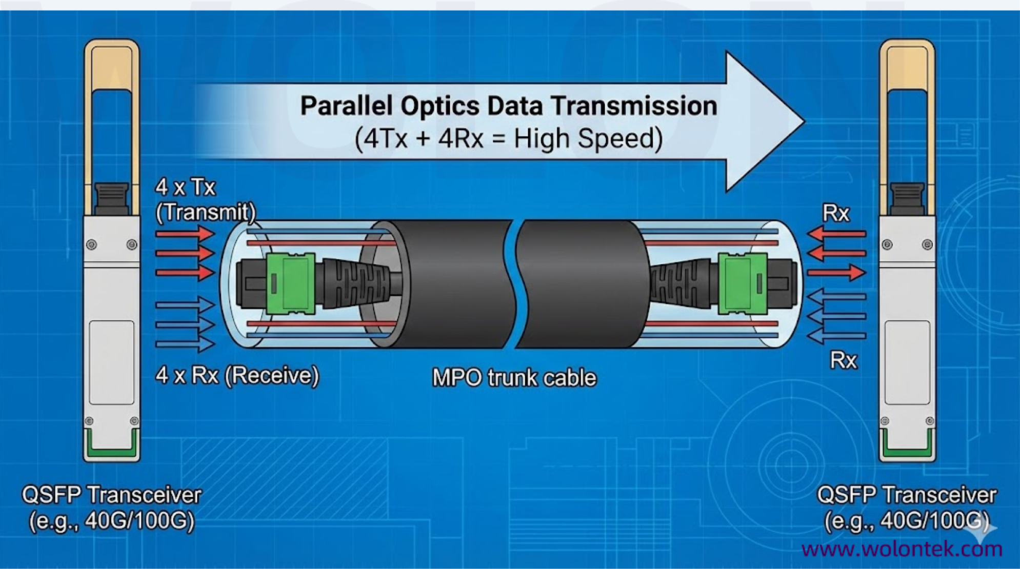
The honest reason data centers love MPO connectors is threefold: space, speed and flexibility. One MPO port replaces many single-fiber ports, freeing rack real estate and drastically reducing panel clutter. Second, MPO enables parallel optics — multiple fibers behaving as a single logical lane — which is how modern 40/100/400G modules move lots of data. Third, an MPO-centric backbone eases migration: you swap cassettes or transceivers rather than re-pull fiber, making data center connectivity upgrades far less painful.
Fiber counts and form factors — choose what matches your roadmap
Common MPO configurations include 8, 12, 16, 24 and higher fiber counts. The 12-fiber MPO is ubiquitous because it maps neatly to many parallel optic standards (for example, breaking out transmit/receive lanes). When planning fiber termination, pick a fiber count that aligns with current transceiver usage and a realistic growth plan — a small buffer of spare fibers today saves a costly re-pull tomorrow.
MTP® Connector vs MPO Connector — the procurement nuance
“MTP” is a branded, higher-precision type of MPO connector. In everyday conversation they’re often treated the same, but in contracts the distinction matters: MTP® implies specific mechanical tolerances and accessories. If you insist on those narrower tolerances for low-loss, repeatable installs, specify MTP®; if you need standards-compliant, vendor-neutral parts, specify MPO connector.
Polarity and gender — small details that determine link sanity
An MPO connector has gender (pinned vs unpinned) and polarity (how fiber positions map from one end to the other). Polarity schemes ensure transmitters land on the correct receiver fibers; gender ensures mating alignment. Treat these as non-negotiable checklist items during design and procurement: wrong polarity or missing pins turns a perfectly installed trunk into a dark link. Labeling and documentation during fiber termination are cheap insurance.
Termination approaches — factory vs field choices
For critical backbones most practitioners choose factory-terminated MPO trunks and pre-built assemblies. Factory termination reduces variability and speeds installation. Field termination is still used for custom lengths or fixes, but requires skill and tooling. A practical hybrid is common: factory trunks for the backbone and MPO-to-LC cassettes at the rack for connectivity to legacy single-fiber transceivers..
Use cases where multi fiber push on wins
-
High-density racks: when port real estate is limited.
-
Parallel optics: when multiple fibers act as a single high-speed lane.
-
Migration planning: when you expect to move from 10G to 40/100/400G without re-pulling cable.
If your architecture demands compact, reconfigurable wiring that supports future optics, MPO connectors are the practical, economical choice.
Common procurement and design pitfalls
Don’t mix APC and UPC polish types in the same channel. Don’t fail to specify MTP® versus generic MPO when tolerance matters. Don’t ignore gender and polarity documentation — those two oversights cause the most avoidable downtime. Finally, don’t buy jumpers without published insertion-loss specs if you care about predictable link budgets. These simple actions save you hours in the field.
Conclusion
A Multi-Fiber Push-On (MPO) connector is not a fancy gadget — it’s a systems decision. When you treat the MPO as the backbone of your fiber termination and data center connectivity strategy (choose the right fiber count, be explicit about MTP® vs MPO, document gender and polarity, and favor factory trunks for mission-critical routes), it turns cabling complexity into manageable modular blocks. The multi fiber push on idea — many channels, one mate — is elegant because it solves practical problems: density, speed and future upgrades. Design deliberately, specify clearly, and the MPO connector will repay you with tidy cabling and fewer surprises.