Verifying optical transceiver firmware and ensuring compatibility is a small set of disciplined checks that prevents big outages. Whether you manage a data-center fabric, campus switches, or carrier transport, a short verification workflow—inspect, back up, validate, test—keeps new modules from becoming downtime vectors. This guide walks you, step-by-step, through practical commands, verification checks, and real-world testing so you can deploy transceivers with confidence.
Why firmware and compatibility matter
Transceiver firmware and host-platform firmware together control module identification, DDM/DOM reporting, power envelopes and vendor authentication. If the module’s firmware or vendor ID isn’t recognised by the switch, the port can refuse to come up (or run unstably). Likewise, mismatched optical specs (wavelength, fiber type, receiver sensitivity) cause high loss or BER even when the link lights up. Treat firmware checks as part of acceptance testing, not an afterthought.
First check — read the module’s current state
Start by reading the transceiver details from the host. Most enterprise switches expose module identity, part number, serial, firmware version and DDM readings via CLI:
-
Cisco / IOS-NX-OS / modular platforms: commands such as show interface transceiver details or the hardware transceiver commands show vendor, part number, serial and DDM. Use these outputs to capture current firmware and diagnostic metrics before any change.
-
Juniper (Junos): show system firmware and related commands report current and available firmware for platform components; use these to confirm the control plane and module bundles.
Back up everything first
Before any upgrade attempt, backup the switch configuration and collect the transceiver firmware image or device flash. Store at least two copies (local archive + secure network share). If your platform supports exporting the module image or configuration snapshot, do that and verify checksums. A clean rollback path reduces upgrade risk and shortens recovery time.
Verify vendor compatibility and vendor-lock policies
Don’t assume any third-party module will work. Many manufacturers publish optics-to-device compatibility matrices and may perform vendor-code checks at insertion. Always look up the exact part number in the platform vendor’s compatibility matrix or optics support pages before installing or updating firmware. If the switch enforces vendor authentication, non-approved modules may be rejected or behave unpredictably. Use the vendor’s official database or API lookup when possible.
Confirm physical and optical compatibility
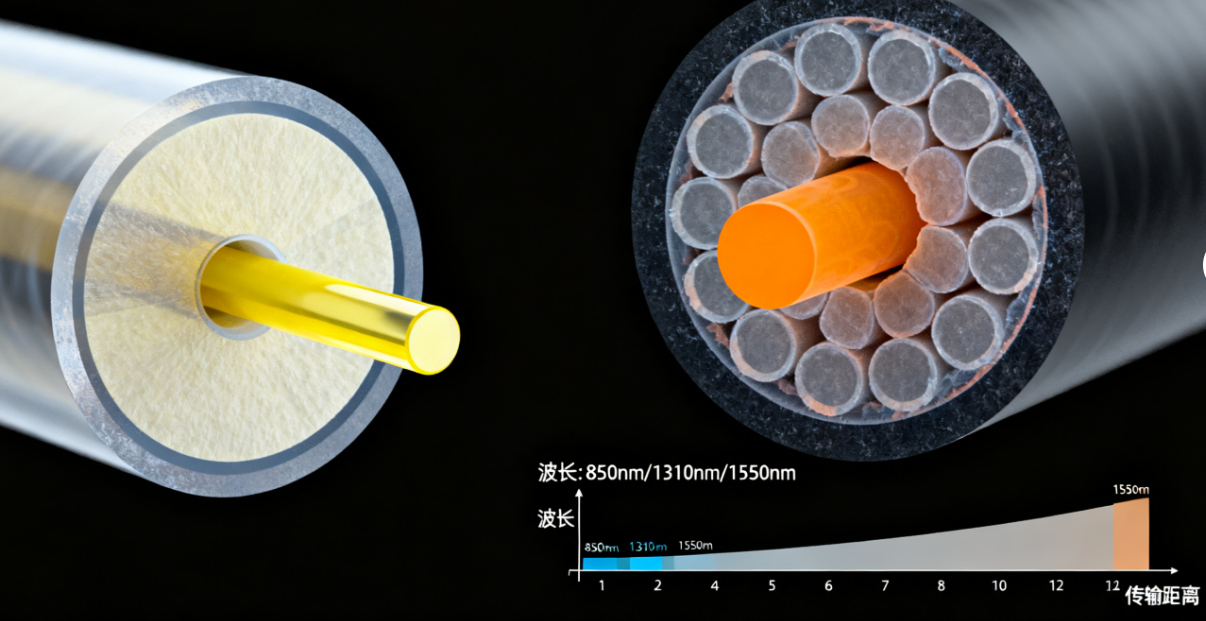
Match form factor (SFP/SFP+/QSFP), fiber type (SM/MM), wavelength and reach to your link plan. Check the module’s TX power vs. receiver sensitivity and calculate a real loss budget including connectors and splices. If the module supports DDM/DOM, verify the reported TX/RX power and temperature fall inside datasheet ranges.
Plan firmware updates deliberately
If an update is needed:
-
Confirm the exact firmware bundle and platform compatibility from the vendor’s release notes.
-
Stage the firmware in a test environment first — ideally on a lab switch of the same model or an isolated port.
-
Use the vendor’s documented install procedure (file names, install commands, reload behavior) and note whether a reload is required. For chassis and modular devices, follow vendor upgrade guides to avoid partial rollouts that leave components mismatched.
Use DDM/DOM and diagnostics to validate health
Digital Diagnostic Monitoring (DDM/DOM) is your fastest immediate health check: it reports real-time TX/RX power, laser bias, temperature and voltage. Retrieve and log those readings before and after any firmware change; anomalies (sudden drop in TX power, rising temperature) flag hardware or calibration issues. DDM is standardized and widely implemented—use it as your primary verification telemetry.
Functional tests — don’t trust only LEDs
After the module is recognised and firmware matches:
-
Run link bring-up and validate baud/protocol (speed, FEC, lanes).
-
Execute a BERT test at operational data rates where possible (10G/25G/100G and above need BER validation).
-
Perform loopback and fiber continuity checks; measure insertion loss with an OLTS or power meter on the operating wavelength.
-
Under load, observe error counters and FEC corrections.
A module that “lights green” but shows elevated BER or FEC corrections is not yet production-ready.
Document and automate
Record every verification: part numbers, firmware revisions, DDM snapshots, BERT results and the final approval sign-off. For scale, script the inventory+DDM pulls (SNMP, vendor APIs or CLI automation) so you can compare before/after snapshots quickly across many ports.
Practical guardrails and troubleshooting tips
-
If a module isn’t recognised, confirm vendor-code enforcement and try a vendor-approved SKU or a platform-compatible third-party with tested certification.
-
If DDM reports strange values after an upgrade, rollback and open a vendor case—some firmware updates change calibration tables.
-
Always test in the lab before mass deployment. Real-world testing often exposes issues that compatibility matrices don’t show.
WOLON product note

If you want modules that simplify this workflow, WOLON’s optical module family (SFP/SFP+/SFP28/QSFP+/QSFP28) ships with full vendor documentation, factory-measured DDM logs and certified compatibility reports for major switching platforms—making verification and deployment faster and less risky. Contact WOLON for datasheets, compatibility matrices and assistance with pre-deployment validation.