Wavelength mismatch is a deceptively simple phrase for a problem that silently defeats optical designs and network links. At its core it means “the light used during fabrication or transmission does not match the light the device expects to see in operation.” In lenses, metasurfaces and Pancharatnam–Berry (PB) elements this creates phase errors and aberrations; in fiber links and transceivers it creates excess loss, bit-error bursts and unstable links. Below I walk through the concrete causes, the symptoms you’ll see in the lab or the field, and practical steps to prevent and correct the issue so your imaging systems and networks behave predictably.
What causes wavelength mismatch?
-
Fabrication vs. operating wavelength mismatch (diffractive optics and PB lenses). Many liquid-crystal PB lenses and diffractive optical elements are patterned or exposed at a specific wavelength. If the operating wavelength differs from the exposure wavelength the local phase profile will be off by a predictable amount, producing strong off-axis aberrations—especially for fast lenses (low f-number) and larger diameters. This effect has been documented and there are dedicated exposure strategies to reduce it.
-
Material dispersion and birefringence. Even when the fabrication wavelength is matched, material refractive index depends on wavelength (dispersion). Birefringent layers or stressed coatings cause different polarization states and resonant modes to shift with wavelength, splitting resonances and rotating polarization in undesired ways.
-
Fiber / link mismatches. Connecting the wrong fiber type (single-mode vs multimode) or mixing core sizes (62.5/125 µm ↔ 50/125 µm) can create large coupling loss because the modal field and numerical aperture no longer match. These modal and coupling losses are a frequent root cause of “mystery” link failures.
-
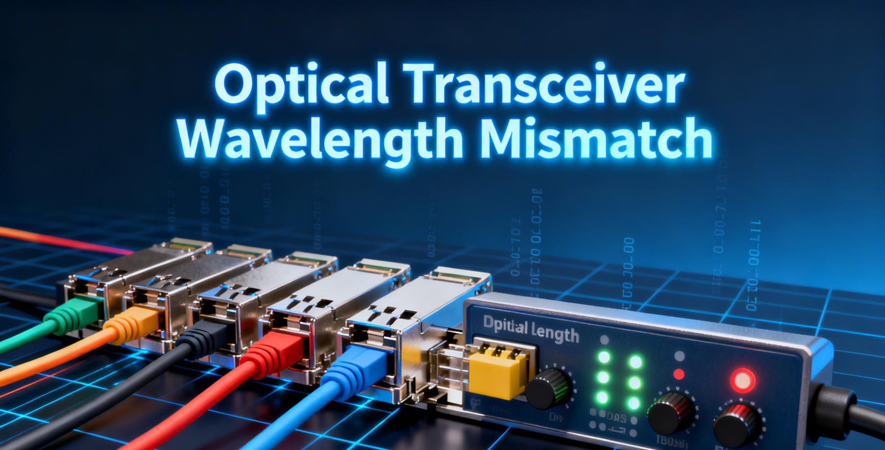
transceiver and receiver specs. Transceivers have center wavelengths, spectral width and power budgets tuned for particular fiber windows. Mismatched wavelengths or incorrect power levels produce no-link conditions or intermittent operation.
Symptoms you will observe
-
Optical imaging systems: increased blur, coma-like edge artifacts, reduced peak intensity at the focal point, color fringing and visible degradation at lens edges. For PB elements these symptoms grow rapidly with aperture size and when the operating wavelength departs from the design wavelength.
-
Fiber links and networks: high insertion loss, no link light-up, alarms from receivers (overload or under-power), very high bit-error rate (BER) or repeated retransmissions, and sudden bit-error bursts during operation.
-
Spectrometers / resonant cavities: split resonance peaks, polarization-dependent resonance shifts, reduced extinction ratio and instability in systems that rely on precise modal alignment.
-
Field testing anomalies: measured loss far exceeding a properly calculated budget despite “good” connectors and splices—often a sign the wrong fiber or Transceiver wavelength is in use.
Real, testable numbers
-
Fiber attenuation: typical multimode attenuation is on the order of ~3.0–3.5 dB/km at 850 nm and ~1.0–1.5 dB/km at 1300 nm; single-mode attenuation is far lower (~0.4–0.5 dB/km at 1310 nm and ~0.2–0.4 dB/km at 1550 nm). Use these baselines when building a loss budget.
-
Core-size mixing penalty: coupling a 62.5 µm multimode core into 50 µm multimode fiber can produce a one-time excess loss on the order of roughly 1–3 dB (test results and manufacturer guidance vary with source type), which may already consume important budget margin. Corning and practical field tests recommend avoiding mixed core sizes where possible.
-
connector and splice figures: expect connector pair losses commonly in the 0.5–0.75 dB range, while a well-executed fusion splice is typically ~0.1–0.3 dB. Compare measured values to these to rule out connector issues.
How to prevent wavelength mismatch (practical checklist)
-
Design-time matching (DOEs, PB lenses, metasurfaces). Specify the operating wavelength early and choose exposure/fabrication wavelength and materials that minimize phase deviation. If you must fabricate at a different wavelength, use multi-exposure or template-multiplexing approaches and pre-compensated profiles to reduce phase errors. Researchers have published exposure-based correction methods for PB lenses that materially reduce aberration in operation.
-
Material and geometry choices. For elements that will operate across a band, select low-dispersion (low dn/dλ) materials or implement achromatic designs (stacked layers, metasurface compensation, or hybrid refractive–diffractive optics).
-
Strict fiber and transceiver matching. Always confirm both ends of the link use the same fiber class (SM vs a specific MM grade), the same core size, and transceivers with matching center wavelengths and compatible launch power. Avoid mixing 62.5 µm and 50 µm multimode fibers in production runs; if unavoidable, measure coupling loss and allow the corresponding margin.
-
Quality testing and measurement. Use calibrated optical power meters, OLTS (optical loss test sets) and multi-wavelength testers to measure insertion loss at the intended operating wavelength(s). Run Bit-Error-Rate Tests (BERT) for high-speed links and verify the link budget against measured attenuation and connector/splice losses. Regular calibration of test gear is essential.
-
Maintenance and inspection. Clean and inspect connectors before every test or deployment. Connector contamination is one of the most common root causes of link faults that mimic wavelength or modal mismatch. Establish a cleaning and inspection schedule and log results.
-
Active correction where needed. In precision optical systems, consider adaptive optics, real-time wavelength tuning (tunable lasers) or electro-optic/thermal post-tuning mechanisms to compensate for small resonance or polarization shifts in situ.
Quick troubleshooting flow
-
Confirm the transceiver labels: wavelength, module type (SR, LR, LX) and intended fiber.
-
Verify fiber type end-to-end and measure loss at the operational wavelength.
-
Clean connectors; remeasure. If loss remains high, inspect for mixed core sizes or broken fibers.
-
If imaging artifacts appear in DOEs or PB lenses, verify fabrication vs operating wavelengths and consult exposure-correction techniques or multi-layer designs.
WOLON product note

For network engineers and system integrators who need transceivers and optical modules that play well with careful wavelength planning, WOLON offers a portfolio of SFP/SFP+/SFP28 and QSFP/QSFP28 optical modules engineered for reliable spectral alignment and tight power budgets. Manufactured and factory-tested to match industry fiber windows and connector standards, WOLO‘s modules come with clear, stamped wavelength and power specifications and factory test reports to simplify installation, minimize mismatch risk and accelerate commissioning. Contact WOLON for datasheets, multi-wavelength test reports, and compliance support for your next deployment.