
n high-speed fiber optic networks, optical signal integrity depends heavily on the physical layer. While network engineers spend considerable time calculating optical power budgets and selecting active transceivers, the overall performance of an entire fiber link can be severely compromised by a seemingly minor detail: the polish type of the fiber optic connector ferrule.
When sourcing and deploying single-mode fiber patch cords, engineers and technicians primarily choose between two industry-standard polish configurations: UPC (Ultra Physical Contact) and APC (Angled Physical Contact).
The decision to use UPC or APC connectors is never a cosmetic or arbitrary choice. It directly dictates critical optical performance metrics, including Return Loss (RL) and Insertion Loss (IL), and determines the reliability of fiber links for specific network applications. This definitive guide elaborates on the core structural differences, optical performance characteristics, and targeted application scenarios of UPC and APC fiber connectors for engineering deployment reference.
Understanding Ferrule End-Face Geometries
To differentiate UPC and APC connectors, it is essential to first understand the core function of the ceramic ferrule—the core component of fiber connectors. The precision-machined ceramic ferrule accurately aligns single-mode fiber cores (typically 9 microns in diameter), ensuring optical signal transmission between connected fibers with minimal obstruction and loss. The polishing method applied to the ferrule end-face is the fundamental factor governing light transmission and reflection behavior at fiber connection joints.
Core Structural Differences Between UPC and APC Connectors
What Is a UPC Connector?
UPC stands for Ultra Physical Contact, an upgraded iteration of the traditional PC (Physical Contact) fiber polish standard. UPC connectors undergo a rigorous, extended high-precision factory polishing process, forming a smooth, slightly domed spherical end-face on the ferrule.
When two UPC connectors are mated in a standard fiber adapter, the highest points of their curved end-faces fit tightly together. This design eliminates nearly all air gaps between paired fiber cores, enabling optical signals to transmit across the connection interface with ultra-low attenuation.
Industry Standard Color Coding: Blue (single-mode fiber housing and boot)
What Is an APC Connector?
APC stands for Angled Physical Contact. Distinct from the vertical spherical surface of UPC connectors, APC ferrules are polished to a precise 8-degree oblique angle—the key design difference that delivers superior anti-reflection performance.
This angled structure completely changes the propagation path of reflected light. When optical signals reach the joint of two mated APC connectors, residual reflected light is deflected outward into the fiber’s surrounding glass cladding, rather than propagating backward along the fiber core to the optical transmitter. This mechanism effectively suppresses back-reflection interference.
Industry Standard Color Coding: Green (single-mode fiber housing and boot)
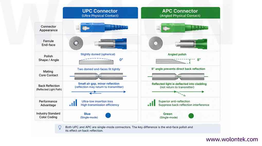
Optical Performance Comparison: Insertion Loss vs Return Loss
The essential technical distinction between UPC and APC connectors lies in two core optical performance parameters: Return Loss and Insertion Loss, which define fiber link signal quality.
1. Optical Return Loss (ORL)
Return Loss quantifies the intensity of light reflected from a fiber connection interface back to the optical transmitter, measured in decibels (dB). A higher absolute dB value indicates better performance, as it means less back-reflected light to interfere with laser source stability and signal purity.
- UPC Connectors: Deliver a typical return loss of 50 dB to 55 dB. While sufficient for most conventional digital network systems, Fresnel reflection still generates minor core back-reflection, limiting performance in high-precision scenarios.
- APC Connectors: Achieve a far superior return loss of 60 dB to 65 dB. The 8-degree angled polish diverts nearly all reflected light into the fiber cladding, minimizing core back-reflection and ensuring ultra-stable signal transmission.
2. Insertion Loss (IL)
Insertion Loss refers to the optical power loss generated when light passes through a mated connector pair, also measured in dB. For this parameter, alower value represents better transmission performance.
Core Verdict: For clean, factory-terminated connectors of qualified quality, UPC and APC deliver nearly identical insertion loss performance, with typical values ranging from ≤0.2 dB to 0.3 dB.
Technical Nuance: The angled profile of APC ferrules theoretically increases alignment difficulty compared to UPC. However, modern high-precision factory termination and standardized adapter sleeves fully eliminate this mechanical deviation, resulting in consistent low-loss performance for both connector types.
Comprehensive Technical Parameter Summary
The table below systematically compares the mechanical structural design and optical performance characteristics of UPC and APC connectors:
| Technical Parameter | UPC (Ultra Physical Contact) | APC (Angled Physical Contact) |
|---|---|---|
| Ferrule End-Face Geometry | Spherical / Slightly Domed (0° perpendicular vertical polish) | Precise 8° angled polish |
| Industry Standard Color | Blue | Green |
| Typical Return Loss | ≥50 dB – 55 dB | ≥60 dB – 65 dB |
| Typical Insertion Loss | ≤0.2 dB – 0.3 dB | ≤0.2 dB – 0.3 dB |
| Reflection Behavior | Reflected light propagates straight back down the fiber core | Reflected light is diverted into the fiber cladding |
| Dust/Dirt Sensitivity | High susceptibility; surface debris creates air gaps and severe back-reflection | Moderate susceptibility; angled face weakens the impact of residual reflection caused by debris |
Application Scenarios: UPC vs APC Deployment Guidelines
Divergent optical properties determine the exclusive application scenarios of UPC and APC connectors in telecommunications and data networking systems. Selecting the correct connector type is critical to long-term network stability.
When to Deploy UPC (Blue Connectors)
UPC connectors are ideal for standard digital optical transmission systems with loose back-reflection tolerance requirements, covering most short-to-medium distance digital data transmission scenarios.
- Enterprise LANs & Data Centers: The mainstream choice for standard Ethernet patching, switching fabric interconnection, and structured cabling in local area networks, meeting the low-loss requirements of digital data transmission.
- Standard Telecom Backbones: Suitable for point-to-point digital data transmission on short and medium-haul telecom backbone links.
- Multimode Fiber Systems: Almost all multimode fiber applications adopt UPC connectors (color-coded beige, aqua, or magenta). Multimode optical signals are less sensitive to back-reflection interference, making UPC’s cost-effective and reliable performance fully sufficient.
When to Deploy APC (Green Connectors)
APC connectors are mandatory for networks carrying analog signals, multi-wavelength multiplexed signals, or high optical power. Excessive back-reflection in these scenarios will cause signal ghosting, phase noise, waveform clipping, and even permanent damage to optical transmitters.
- FTTH/FTTx PON Deployments: Passive Optical Network (PON) systems for fiber-to-the-home integrate voice, data, and analog video services on a single single-mode fiber. APC’s ultra-high return loss ensures zero distortion of analog video signals and stable multi-service co-transmission.
- WDM & DWDM Systems: Wavelength Division Multiplexing systems require stable optical power for each independent wavelength channel. APC connectors eliminate back-reflection crosstalk, ensuring the accuracy of multi-wavelength signal transmission.
- CATV Cable Television Networks: Analog video distribution systems are extremely sensitive to reflected light noise. APC’s anti-reflection design effectively avoids screen ghosting, flicker, and signal attenuation caused by core back-reflection.
- Next-Generation Coherent Optical Systems: Ultra-high-speed networks (400G, 800G, 1.6T) using advanced coherent modulation technologies require ultra-clean transmission paths. APC connectors minimize phase disturbance and guarantee high-order modulation signal integrity.

Critical Deployment Rule: Never Mix UPC and APC Connectors
The most fundamental and non-negotiable rule of fiber installation and maintenance is: Never mate a UPC connector with an APC connector. This mismatched connection causes irreversible performance loss and hardware damage.
UPC ferrules feature a vertical 0° spherical end-face, while APC ferrules adopt an 8° angled end-face. Mating these two mismatched connectors in a standard alignment sleeve fails to achieve full core contact:
Mating Interface Profile Schematic
UPC Ferrule: ||——— (Vertical flat spherical interface)
APC Ferrule: //——— (8° angled interface)
Mismatch Result: Air gaps form on one side of the joint, while excessive extrusion pressure occurs on the opposite side.
This structural mismatch leads to two severe consequences:
- Extremely High Insertion Loss: Unavoidable air gaps at the mismatched interface cause massive optical power loss, with insertion loss often exceeding 4.0–5.0 dB, directly resulting in link failure or signal interruption.
- Permanent Physical Damage: The sharp edge of the angled APC ferrule will scratch and deform the smooth domed surface of the UPC ferrule. This damage is irreversible, permanently reducing the polishing precision and optical performance of both connectors.
Engineering Best Practice: Always verify the polish type of patch cords, adapter panels, and equipment bulkheads before connection. Strictly follow the matching rule: blue-to-blue (UPC) and green-to-green (APC).
Ensure 100% End-Face Compatibility
Don’t risk high attenuation or permanent hardware damage caused by mismatched polish types. Consult with our engineering team to secure IEC-compliant UPC and APC single-mode assemblies tailored to your exact optical budget.
Request Technical ConsultationCan I use the same fiber inspection probe tip for UPC and APC connectors?
No, you must use geometry-specific adapter tips. Because an APC ferrule is polished at an 8-degree angle, using a standard 0-degree UPC probe tip will result in an out-of-focus image. The focal plane will only capture a fraction of the ferrule, making it impossible to accurately assess the cladding and core zones. Always swap to an 8-degree angled probe tip when inspecting green APC connectors to ensure the entire end-face is in focus.
How do you clean APC vs UPC fiber optic connectors properly?
The fundamental cleaning chemistry is the same, but the mechanical technique requires attention to geometry. For both, the industry standard is the “dry-cleaning first, wet-to-dry second” method. You can use standard lint-free cassette cleaners (like reel-based cleaners) for both types by sweeping the ferrule in a figure-eight motion. However, if you use “One-Click” pen cleaners, ensure the tool is rated for the specific ferrule diameter ($1.25 \text{ mm}$ for LC/MU, or $2.5 \text{ mm}$ for SC/FC) and properly seats against the angled surface of the APC ferrule to ensure the cleaning thread wipes the core effectively.
What are the IEC 61300-3-35 fiber optic inspection standards for UPC and APC?
IEC 61300-3-35 is the global standard defining pass/fail criteria for fiber optic connector end-faces. The standard divides the ferrule into four zones: Core (Zone A), Cladding (Zone B), Adhesive (Zone C), and Contact (Zone D). For single-mode fibers (both UPC and APC), the standard mandates absolute zero tolerance for scratches or defects within the Core zone (0 to 25 microns). Both polish types must pass this exact same strict criteria before being mated to prevent signal degradation.
Does dust or dirt affect UPC or APC connectors more?
While both are highly sensitive, they fail in slightly different ways. On a UPC flat connector, dust creates a microscopic air gap between the two ferrules. This air gap immediately destroys Return Loss (RL), causing light to reflect directly back into the laser source. On an APC angled connector, the spring-loaded mating force can cause debris to offset the precise 8-degree alignment. This rotational misalignment primarily degrades Insertion Loss (IL). In both cases, microscopic dust—often invisible to the naked eye—causes critical network failures.
What happens if you mate dirty fiber connectors without inspecting them first?
Mating uninspected connectors violates the fundamental “Inspect, Clean, Inspect” industry rule and risks permanent hardware damage. When two ferrules are mated inside an adapter, they connect with roughly 1 kilogram (2.2 lbs) of physical force. If microscopic silica dust or dirt is present on the end-face, this high-pressure mating will crush the debris directly into the glass core, causing permanent “pitting” or scratches. Once the glass is pitted, the connector cannot be cleaned; it must be cut off and re-terminated, or the entire patch cord must be replaced.
De-Risk Your Optical Supply Chain
From ultra-low loss APC drops for FTTx deployments to high-density UPC data center trunks, WolonFiber manufactures zero-compromise optical pathways that bypass extended manufacturing timelines.