
Author: WolonFiber Technical Engineering Team Release Date: June 2026 Read Time: 7-8 min read
As modern networks evolve to support AI-driven compute clusters, hyperscale cloud facilities, and high-frequency 5G infrastructures, traditional single-fiber or duplex patching configurations (such as LC and SC) face physical density limits. In modern architectures—ranging from 40G and 100G migration paths to advanced 400G and 800G parallel optics networks—maximizing bandwidth within tight rack footprints is a primary engineering requirement.
However, a persistent pain point remains within the fiber optics industry: many field technicians and deployment vendors frequently confuse the generic mpo fiber connector standard with the premium, trademarked MTP® variant. This misunderstanding often leads to critical errors in polarity configuration, component selection, and optical loss budgeting during data center deployments.
This comprehensive technical guide provides an engineering-driven breakdown of the MPO/MTP ecosystem, detailing its structural mechanics, optical performance tiers, link polarity standards, and global supply chain integration practices.
What Are MPO and MTP Connectors? Core Concepts & Definitions
To understand how high-density structured cabling scales, one must distinguish between generic industry standards and optimized commercial iterations.
1. The MPO Connector Definition
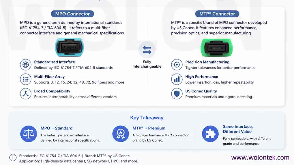
MPO stands for Multi-Fiber Push-On. It is a generic term for a multi-fiber connector architecture defined by international standards bodies. It complies with strict industry regulations, including IEC-61754-7 (international standard) and TIA-604-5 (also known as FOCIS 5 in the United States). The standard mpo optical connector uses a single mechanical housing to consolidate multiple optical strands, most commonly arranged in arrays of 8, 12, 24, or 48 fibers.
2. The MTP Connector Definition
MTP® is a registered trademark of US Conec Ltd. It represents a premium commercial version of the MPO connector that is engineered to tighter tolerances. While it remains fully compliant with generic MPO standards, the MTP connector incorporates significant mechanical enhancements—such as a floating ferrule, elliptical guide pins, and a removable housing—designed to improve long-term optical reliability and performance.
3. Intermateability and Structural Differences
Are they compatible? Yes. A generic fiber mpo connector and a branded MTP connector can physically mate within a standard alignment sleeve. However, their mechanical stability and optical loss attributes occupy different performance tiers. The MTP connector reduces mechanical wear and insertion loss variation compared to generic alternatives during repeated mating cycles.
4. The High-Density Performance Paradigm
Compared to traditional LC duplex adapters, an mpo 12 connector array can reduce physical panel footprint requirements by up to 75%. This spatial consolidation drastically reduces cable tray congestion, optimizes cold-aisle thermal management, and simplifies fiber path trace operations.
5. Core Optical Parameter Matrix
The table below illustrates the optical performance tiers available across standard MPO, standard MTP, and premium MTP Elite configurations:
| Connector Type / Tier | Multimode (OM3/OM4/OM5) Typ/Max IL | Singlemode (OS2) Typ/Max IL | Standard Return Loss (RL) | Sourcing Context |
| Standard MPO Connector | $0.20 \text{ dB} / \le 0.60 \text{ dB}$ | $0.25 \text{ dB} / \le 0.75 \text{ dB}$ | $\ge 20 \text{ dB} \text{ (MM)} / \ge 50 \text{ dB} \text{ (SM UPC)}$ | Baseline commercial enterprise networks |
| Standard MTP Connector | $0.15 \text{ dB} / \le 0.40 \text{ dB}$ | $0.15 \text{ dB} / \le 0.60 \text{ dB}$ | $\ge 20 \text{ dB} \text{ (MM)} / \ge 60 \text{ dB} \text{ (SM APC)}$ | Standard data center backbones |
| MTP Elite® (Premium Tier) | $0.10 \text{ dB} / \le 0.35 \text{ dB}$ | $0.10 \text{ dB} / \le 0.35 \text{ dB}$ | $\ge 25 \text{ dB} \text{ (MM)} / \ge 65 \text{ dB} \text{ (SM APC)}$ | AI compute clusters, 400G/800G fabrics |
Key Structural & Optical Features
Deploying mpo connector fiber assemblies in high-speed links requires a precise understanding of four core technical parameters:
1. Connector Gender (Pins vs. No Pins)
Unlike single-fiber connectors that rely on split-ceramic alignment sleeves inside an adapter, the mpo mtp connector system achieves alignment via precision physical mating pins.
- Male Connectors (Pinned): Feature two precise metal guide pins protruding from the ferrule face.
- Female Connectors (Unpinned): Feature two precise alignment guide holes drilled into the ferrule face.
To prevent permanent damage to the polished optical fibers, a male connector must always mate with a female connector. Never mate male-to-male (pins will collide and crush) or female-to-female (lack of alignment will cause extreme insertion loss).
2. Connector Orientation (Key Up vs. Key Down)
Every MPO/MTP connector housing features a raised tab on one side, known as the Key. The orientation of this key when inserted into an adapter determines how the internal fiber array maps across the link:
- Key Up / Key Down (Opposite/Direct): Connectors mate with the key facing up on one side and down on the other. Fiber 1 maps directly to Fiber 1 on the opposing end.
- Key Up / Key Up (Aligned/Crossed): Both keys face upward inside the adapter. This mirrors the fiber array, mapping Fiber 1 on one end to the highest fiber position (e.g., Fiber 12) on the other.
3. End-Face Polishing Types (UPC vs. APC)
The treatment of the ferrule tip governs back-reflection performance:
- UPC (Ultra Physical Contact): Features a perpendicular, slightly domed surface finish ($0^\circ$). Typically color-coded Blue for single-mode or Aqua/Magenta for multimode.
- APC (Angled Physical Contact): Polished at a precise $8^\circ$ angle. This design deflects reflected light out of the core and into the fiber cladding, achieving a return loss of $\ge 60\text{ dB}$. Single-mode APC connectors are globally color-coded Green.
4. Polarity Management
Polarity defines the system layout that ensures the transmitter (Tx) maps to the correct receiver (Rx) at the opposite end of the link. The TIA-568 standard defines three standardized configurations for mpo mtp fiber connector trunk cables:
- Type A (Straight-Through): Uses Key Up to Key Down adapters with a straight-through pin mapping (1-to-1, 2-to-2, etc.).
- Type B (Fully Flipped): Uses Key Up to Key Up adapters, reversing the entire fiber sequence (1-to-12, 2-to-11, etc.). This configuration is required for direct transceiver-to-transceiver linking in parallel optics (e.g., 40G-SR4, 100G-SR4).
- Type C (Pair-Flipped): Uses Key Up to Key Down adapters but flips each adjacent pair of fibers (1-to-2, 2-to-1, 3-to-4, 4-to-3). This layout is typically used in legacy duplex migration schemes.
Core Advantages of MPO/MTP Connectors
Evaluating high-density infrastructure investments requires assessing both generic MPO capabilities and premium MTP mechanical optimizations.
1. General Sourcing Advantages of MPO Options
- Ultra-High Density: Packs massive capacity into minimal space to optimize rack footprint layout.
- Rapid Deployment Timelines: Pre-terminated factory trunks reduce on-site splicing labor by up to 80-90%.
- Standardized Interoperability: Broad multi-vendor compatibility across global telecom network hardware.
2. Unique Optimized Advantages of MTP Connectors
- Removable Housing for Field Modification: MTP housings can be disassembled in the field without damaging the internal ferrule. This allows technicians to shift connector gender (adding or removing guide pins) or reconfigure polarities on-site, reducing supply chain delays.
- Floating Ferrule Architecture: The internal MT ferrule can float independently within the outer housing. This design maintains physical fiber contact under tensile load, preventing signal disruption when cables are pulled or disturbed in dense patch trays.
- Elliptical Guide Pin Geometries: MTP connectors replace traditional round pins with highly polished elliptical guide pins. This profile reduces wear on the matching guide holes, maintaining precise alignment over hundreds of mating cycles.
- Advanced Spring and Metal Pin Clamp Construction: A heavy-duty internal spring assembly evenly distributes physical force across the entire multi-fiber array, while a integrated metal pin clamp protects the delicate fiber ribbon from breaking under compressive stress.
Validate Your High-Density Optical Link Budgets
Avoid polarity errors and high insertion loss penalties in your 100G/400G deployments. Contact our engineering lab to access full 3D interferometer metrics and receive customized MPO/MTP test samples built to your exact layout specifications.
Request Engineering ConsultationIntroduction to the MT Ferrule
The core optical component of any fiber optic mpo connector is the internal MT (Mechanical Transfer) Ferrule.
  +---------------------------------------+
  |  ( ) [ . . . . . . . . . . . . ] ( )  |  <-- 12-Fiber MT Array Face
  +---------------------------------------+
    ▲                ▲                ▲
 Guide Hole     Fiber Cores       Guide Hole
- Material Composition: Unlike standard single-fiber connectors that use zirconium ceramic ferrules, MT ferrules are molded from a high-precision glass-filled polymer material (typically polyphenylene sulfide, or PPS).
- Dimensions and Spacing: A standard Base-12 ferrule aligns 12 individual fibers in a parallel row with an exact pitch of $250 \text{ }\mu\text{m}$ (microns) between fiber centers.
- Engineering Function: The MT ferrule must hold all internal fibers in precise alignment simultaneously. A microscopic deviation of even $1 \text{ }\mu\text{m}$ in position can cause significant attenuation across the entire multi-fiber link.
What exactly is an MT ferrule?
An MT (Mechanical Transfer) ferrule is a multi-fiber, high-precision plastic ferrule that aligns multiple fibers via metal guide pins and holes. It serves as the core internal alignment component for all MPO and MTP connector styles.
How do you clean MPO/MTP connectors correctly?
Multi-fiber connectors are highly susceptible to dust contamination. The industry-standard practice is the “Inspect, Clean, Inspect” cycle using dry-cleaning pen tools (such as One-Click cleaners) rated for $1.25\text{ mm}$ or $2.5\text{ mm}$ multi-fiber footprints. If persistent oils remain on the end-face, use an optical-grade solvent on a lint-free wipe, followed immediately by a dry wipe cycle. Always inspect the ferrule face with an optical probe before mating.
Can MTP connectors switch gender in the field?
Yes, provided you are using authentic US Conec MTP connectors designed with removable outer housings. By removing the outer sleeve with a specialized tool, you can install or remove the internal guide pin clamp to switch the connector between male and female configurations without cutting or re-terminating the fiber.
Are MPO and MTP connectors fully compatible? What are the key differences?
They are fully intermateable mechanically. The difference lies in their performance tolerances. The MTP connector features mechanical design improvements—including a floating ferrule, elliptical pins, and a removable housing—that yield lower insertion loss metrics and better mechanical durability than standard generic MPO connectors.
Can MPO/MTP connectors interface directly with standard LC/SC connectors?
Not directly. Because their physical dimensions and alignment methods differ completely, you cannot plug an MPO trunk into an LC patch panel. Interfacing requires a passive conversion component, such as a pre-terminated MPO-to-LC cassette module or a fan-out breakout harness cable.
Can MPO/MTP connectors with different internal fiber counts be mated?
No. You cannot mate a Base-12 MPO connector with a Base-24 or Base-16 connector. Their internal fiber positions and guide pin spacings do not align correctly, and attempting to mate them will cause severe insertion loss, signal disruption, and potential physical damage to the polished glass faces.
Conclusion & Strategic Sourcing Recommendations
Managing high-density physical layers requires a balanced approach to performance and value. For basic enterprise routing or low-speed legacy links, standard MPO connectors offer a cost-effective solution. However, for mission-critical paths—such as multi-tier cloud fabrics, AI compute clusters, and 400G/800G core networks—specifying premium MTP or MTP Elite solutions is essential to preserve thin optical loss budgets.
As networks continue to scale, diversifying your physical layer supply chain helps mitigate risks. Working with an agile international manufacturing partner like WolonFiber allows you to source premium, factory-terminated high-density interconnects without the extended lead times often associated with domestic Tier-1 vendors.
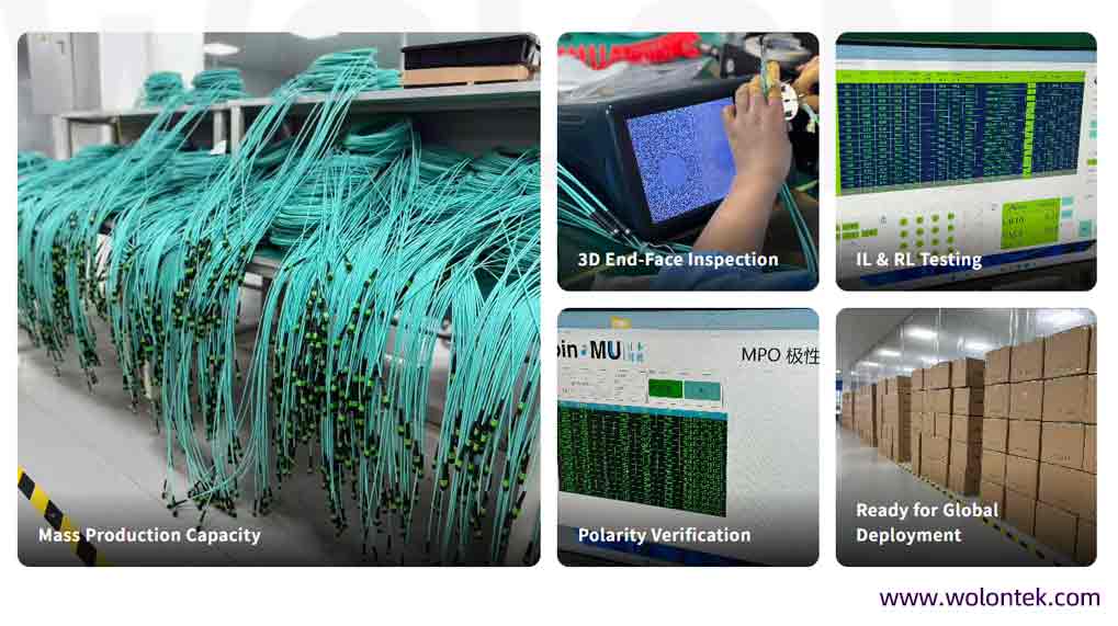
Operating three advanced manufacturing facilities in Wuhan’s Optics Valley with a specialized workforce of 400 to 500 optical technicians, WolonFiber builds custom MPO and MTP trunk cable assemblies designed to meet strict Western data center engineering tolerances. By pairing premium, low-loss MT ferrules with comprehensive 100% 3D interferometer end-face geometry testing, WolonFiber delivers reliable performance for high-speed network upgrades.
Bypass Factory Bottlenecks for Your Next Infrastructure Upgrade
Whether your deployment requires custom-staggered MPO breakout assemblies, specific Type B polarity configurations, or high-volume Base-12/Base-24 data center trunk lines, our engineering team builds to your exact network specifications.