
Patch Cable vs. Crossover Cable: Wiring Schematics and Use Cases
The internal wiring setup of Ethernet cables controls how they work and where you can use them. Know the pin mapping and color coding standards. This helps you pick the right cable type for your network and avoid connection problems.
Understanding the Two Wiring Standards: T568A and T568B
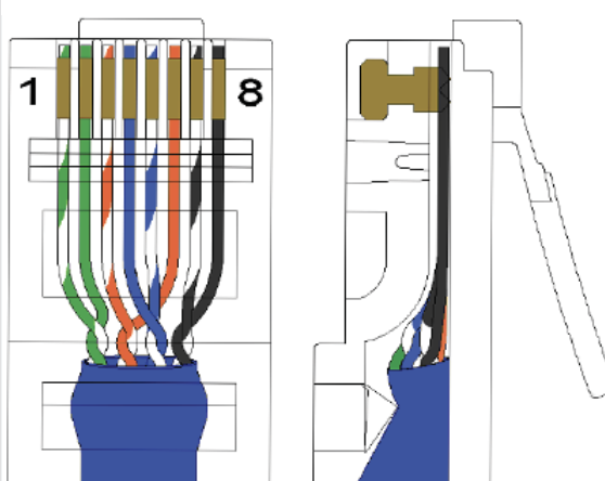
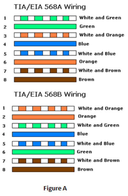
First, learn the two wiring schemes that make up Ethernet cabling: T568A and T568B. These standards show the exact order the eight colored wires inside an Ethernet cable connect to the pins in an RJ45 connector.
T568A Color Sequence (pins 1 through 8):
1. White/Green
2. Green
3. White/Orange
4. Blue
5. White/Blue
6. Orange
7. White/Brown
8. Brown
T568B Color Sequence (pins 1 through 8):
1. White/Orange
2. Orange
3. White/Green
4. Blue
5. White/Blue
6. Green
7. White/Brown
8. Brown
The main difference? The orange and green pairs sit in different positions. In T568A, the green pair sits on pins 1-2. In T568B, the orange pair takes this spot. Both standards work the same for network transmission. Your choice depends on regional preferences, existing setup, or company policies. T568B dominates commercial setups across North America. T568A appears more in homes and government buildings.

Patch Cable Wiring Configuration
Patch cables (also called straight-through cables) use identical wiring on both ends. Wire one end using T568A? The other end also uses T568A. The same goes for T568B—both connectors follow the same color order.
Pin-to-Pin Mapping in Patch Cables:
– Pin 1 → Pin 1
– Pin 2 → Pin 2
– Pin 3 → Pin 3
– Pin 4 → Pin 4
– Pin 5 → Pin 5
– Pin 6 → Pin 6
– Pin 7 → Pin 7
– Pin 8 → Pin 8
This simple mapping means the white/orange wire on pin 1 of connector A connects to pin 1 of connector B. The orange wire on pin 2 of connector A connects to pin 2 of connector B. This pattern continues across all eight pins.
Fast Ethernet (100 Mbps) uses just four of the eight wires to transmit data—those on pins 1, 2, 3, and 6. Gigabit Ethernet and faster speeds use all eight wires at once for two-way communication. This makes proper connection of all pins critical for best performance.
Functional Pin Assignments:
– Pins 1 & 2: Transmit Data (TX+ and TX- in differential signaling)
– Pins 3 & 6: Receive Data (RX+ and RX- in differential signaling)
– Pins 4 & 5: Bidirectional Data Pair 3 (used in Gigabit and higher)
– Pins 7 & 8: Bidirectional Data Pair 4 (used in Gigabit and higher)
The transmit and receive functions work in pairs using differential signaling. The “+” and “-” marks show the positive and negative signals that travel together. This cuts down electromagnetic interference and improves signal quality.
Crossover Cable Wiring Configuration
Crossover cables use different wiring standards on each end—one connector uses T568A while the other uses T568B. This planned mismatch swaps the transmit and receive pairs. Two similar devices can now talk to each other without a switch or hub in between.
Pin-to-Pin Mapping in Crossover Cables:
– Pin 1 → Pin 3
– Pin 2 → Pin 6
– Pin 3 → Pin 1
– Pin 4 → Pin 4
– Pin 5 → Pin 5
– Pin 6 → Pin 2
– Pin 7 → Pin 7
– Pin 8 → Pin 8
See how pins 1 and 2 (the transmit pair on one end) connect to pins 3 and 6 (the receive pair on the other end)? At the same time, pins 3 and 6 (receive pair on one end) connect to pins 1 and 2 (transmit pair on the other end). This crossover lets device A’s transmitter connect to device B’s receiver, and the other way around.
The orange and green pairs swap positions between the two ends. Look at a crossover cable up close. On one end, the white/orange and orange wires sit on pins 1-2. On the other end, the white/green and green wires take those same spots.
Visual Wire Swapping:
– End A (T568A): White/Green on pin 1, Green on pin 2
– End B (T568B): White/Orange on pin 1, Orange on pin 2
– End A (T568A): White/Orange on pin 3, Orange on pin 6
– End B (T568B): White/Green on pin 3, Green on pin 6
Complete Wiring Schematics Reference
Here are the complete wiring diagrams for making your own cables or fixing existing ones:
Straight-Through Patch Cable Schematic:
Both ends: T568A or Both ends: T568B
Pin 1 ←→ Pin 1
Pin 2 ←→ Pin 2
Pin 3 ←→ Pin 3
Pin 4 ←→ Pin 4
Pin 5 ←→ Pin 5
Pin 6 ←→ Pin 6
Pin 7 ←→ Pin 7
Pin 8 ←→ Pin 8
Crossover Cable Schematic:
End A: T568A ←→ End B: T568B
Pin 1 ←→ Pin 3
Pin 2 ←→ Pin 6
Pin 3 ←→ Pin 1
Pin 4 ←→ Pin 4
Pin 5 ←→ Pin 5
Pin 6 ←→ Pin 2
Pin 7 ←→ Pin 7
Pin 8 ←→ Pin 8

Look at these schematics and note that pins 4, 5, 7, and 8 stay straight-through even in crossover cables for traditional Fast Ethernet. These pins carry the extra data pairs needed for Gigabit speeds. They don’t need crossing in standard crossover setups.
Use Case Comparison and Application Scenarios
Pick between patch and crossover cables based on the types of devices you’re connecting. Here’s the basic rule: different device types need patch cables. Similar device types need crossover cables.
Comprehensive Use Case Comparison:
|
Cable Type |
Wiring Standard |
Pin Mapping |
Primary Use Cases |
Specific Examples |
|---|---|---|---|---|
|
Patch Cable (Straight-Through) |
T568A ↔ T568A OR T568B ↔ T568B |
1→1, 2→2, 3→3, 6→6, 4→4, 5→5, 7→7, 8→8 |
Connects different device types |
PC to switch, Switch to router, PC to wall jack, Router to modem |
|
Crossover Cable |
T568A ↔ T568B |
1→3, 2→6, 3→1, 6→2, 4→4, 5→5, 7→7, 8→8 |
Connects similar device types |
PC to PC, Switch to switch, Router to router, Hub to hub |
Real-World Connection Examples
Example 1: Office Workstation Setup (Patch Cable)
You’re setting up a new employee workstation in an office with structured cabling. The wall has an RJ45 jack the facilities team installed. You need to connect the employee’s desktop computer to the network.
Solution: Use a patch cable (both ends wired T568B, matching your company’s standard). Connect from the computer’s network interface card (NIC) to the wall jack. The wall jack connects through in-wall cabling to a patch panel in the server room. Another T568B patch cable connects from the patch panel to an open port on the network switch.
Example 2: Home Network Expansion (Patch Cable)
Your home router has four Ethernet ports. You have six devices that need wired connections. You buy an 8-port network switch to expand connectivity.
Solution: Use a patch cable to connect from one of the router’s LAN ports to the switch’s uplink port (or any port on a managed switch). This creates a single extended network. Then use more patch cables to connect each of your six devices to the switch’s remaining ports.
Example 3: Emergency File Transfer (Crossover Cable – Legacy)
Your main file server failed. You need to transfer backup files fast from an old desktop computer to a replacement server. Neither computer has wireless. The network switches are offline during infrastructure maintenance.
Solution: Both computers have older NICs without auto-MDI-X? Use a crossover cable to connect their Ethernet ports. Set both computers with static IP addresses on the same subnet (for example, 192.168.1.10 and 192.168.1.11 with subnet mask 255.255.255.0). Enable file sharing on the source computer. Access the shared folder from the destination computer to complete the transfer.
Device Type Classification for Cable Selection
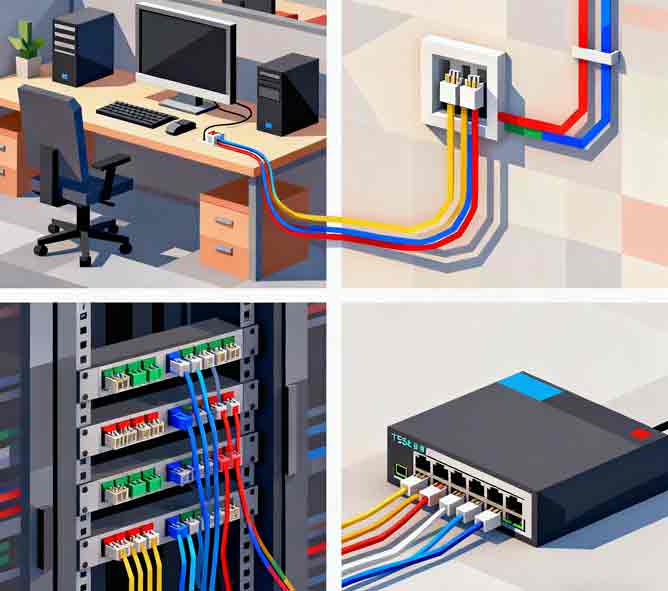
Know which devices fall into which category. This helps you make quick cable choices:
Devices Needing Patch Cables When Connected Together (different device connections):
– Computer/Server ↔ Switch
– Computer/Server ↔ Hub
– Switch ↔ Router
– Router ↔ Modem
– Access Point ↔ Switch
– IP Camera ↔ Switch
– VoIP Phone ↔ Switch
– Any endpoint device ↔ Network infrastructure device
Devices Needing Crossover Cables When Connected Together (similar device connections, if lacking auto-MDI-X):
– Computer ↔ Computer
– Switch ↔ Switch
– Router ↔ Router
– Hub ↔ Hub
– Router ↔ PC (some router models)
Here’s the basic idea: devices that transmit and receive on the same pin numbers need crossover cables to swap these functions. Devices made to work together (like computers and switches) already have matching pin setups. They just need straight-through patch cables.
Practical Tips for Cable Management
Standardize on One Wiring Scheme: Pick either T568A or T568B for all your patch cables and stick with it. T568B is more common in commercial setups. Consistency cuts down errors and makes troubleshooting easier.
Label Crossover Cables Well: Crossover cables serve special purposes and look almost the same as patch cables on the outside. Mark them with colored tape, labels, or buy cables with pre-marked crossover indicators. This stops you from using them in standard connections by mistake.
Keep a Mixed Inventory: Even with modern auto-sensing equipment, keep a few crossover cables on hand. You’ll need them for legacy device support, emergency direct connections, or working with older equipment that lacks auto-MDI-X.
Test Before Deployment: Making your own cables? Use a cable tester to check proper pin-to-pin connections before putting cables into production. Wrong wiring can cause on-and-off connectivity problems that are hard to fix later.
Document Your Infrastructure: Keep records of which wiring standard (T568A or T568B) you’ve used for your structured cabling. This paperwork proves valuable during expansions, troubleshooting, or coordinating with contractors.
Understanding these wiring schematics and use cases helps you design efficient networks. You can fix connectivity problems fast and pick the right cables for any network situation you face.
