
IntroductionLC fiber connectors are the quiet workhorses of modern networks. As a small-form-factor (SFF) interface, LC has become the default duplex connector in enterprise LANs, telco closets, and data-center topologies because it balances density, repeatability, and cost. This guide walks through what “LC” means, the traits that make it pervasive, and the concrete LC-based solutions you’ll specify, buy, or install — from jumpers and uniboot cords to adapters, attenuators, and Transceiver interfaces. The goal here is practical: clear, vendor-neutral guidance you can use immediately when designing or maintaining an LC wiring plant.

What does “LC” mean in fiber optics?
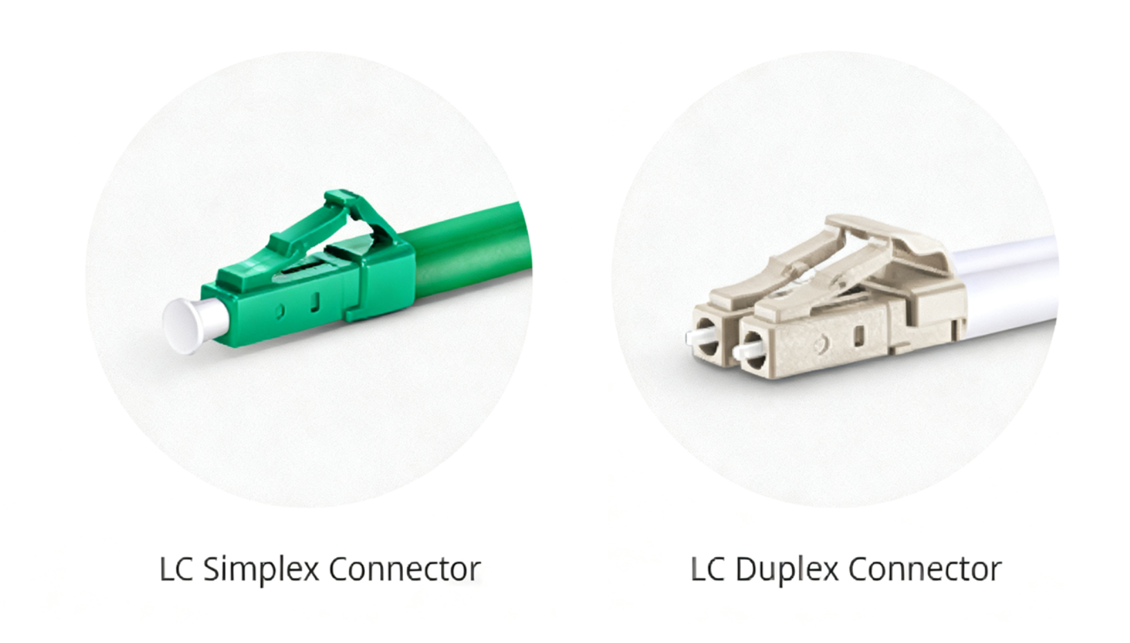
“LC” originates from Lucent Connector — the small-form connector first developed for telecom use that later found broad adoption across data communications equipment. Its defining mechanical feature is a 1.25 mm ceramic ferrule, roughly half the diameter of the older SC/ST ferrules. That smaller ferrule (and the compact duplex housing that pairs two ferrules side-by-side) makes it possible to double port density on panels and transceivers without sacrificing alignment accuracy. LC designs are standardized so well-made parts from different manufacturers will mate reliably when produced to spec.
What are the characteristic strengths of LC connectors?
Below are the practical characteristics that explain why LC remains ubiquitous.
-
High density, small footprint. The 1.25 mm ferrule and duplex form factor let you fit many more ports into a 1U panel or small transceiver package — a decisive advantage in dense racks and SFP-class optics.
-
Mechanical retention and ease-of-use. LC uses a push-pull latch that’s quick to engage and secure in typical patch panels and SFP ports; it’s designed for repeated matings without accidental release.
-
Low insertion loss when done right. A well-made LC termination typically contributes only a few tenths of a decibel of loss per mated pair; industry practice commonly plans for about 0.1–0.3 dB per connector when calculating loss budgets. Factory-terminated and polished connectors usually give the most consistent results.
-
Polish types and return loss behavior. LC connectors are available with different end-face polishes — PC/UPC for general single-mode data links, APC for angled contacts where very low back-reflection is needed (for example analog links or sensitive, long-haul DWDM segments). Industry guidance places typical return-loss targets for UPC around –50 dB and for APC near –60 dB. Choosing the correct polish is a simple way to prevent hard-to-find optical problems.
-
Versatility in formats. You’ll see LC in simplex and duplex, unibody and multi-piece designs, 2.0/3.0 mm boot versions, and specialized short “behind-the-wall” (BTW) or 900 µm-buffered variants intended for low-clearance terminations.
What do we mean by “LC fiber solutions”?
LC fiber solutions are far more than a single connector type. Over time, the LC family has grown into a full ecosystem—connectors, sophisticated patch-cable assemblies, adapters, distribution panels, and attenuators—that forms the backbone of modern telecommunications and LAN infrastructure. Networks choose LC for one core reason: it delivers high port density without compromising repeatability or performance.
LC connector solutions
LC connectors fall into two practical families based on where they’re used: jumper (patch-cord) terminations and Behind-the-Wall (BTW) terminations.
• LC Jumper connectors — These are the familiar terminations at the ends of patch cords. They are manufactured to suit different cable diameters (commonly 1.5–2.0 mm for high-density patching, and 3.0 mm for more ruggedized cable constructions). Jumper LC connectors are available in simplex (single fiber) and duplex (two fibers) formats; their compact bodies are designed to minimize footprint while providing reliable mechanical latching and repeatable optical alignment.
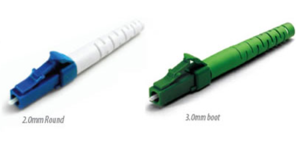
• LC Behind-the-Wall (BTW) connectors — BTW LCs are shortened variants intended for 0.9 mm buffered fiber and are typically used for internal equipment wiring or tight-clearance terminations. The unibody BTW design reduces part count and simplifies routing inside equipment chassis and patch panels.
LC patch cable (jumper) solutions
Data centers and enterprise closets use a variety of LC patch cords tailored to specific operational needs—from space saving to performance margins.
• Standard LC-LC patch cables — The LC-LC duplex jumper is now a common industry default, favored for its small footprint and stable latching. These jumpers come in single-mode (OS1/OS2) and multimode (OM1–OM5) variants to match link requirements.
• Uniboot (high-density) LC cables — Uniboot designs enclose two fibers in a single round jacket that terminates into one compact boot, reducing cable bulk by roughly 50%. Enhanced uniboots add push-pull tabs and polarity-switching features, allowing technicians to reverse TX/RX orientation without re-patching—an ergonomic win during installs and migrations.

• Ultra-low-loss (ULL) assemblies — Where every decibel matters, ULL jumpers use higher-grade connectors and one-piece bodies to achieve very low insertion loss (typical marketed values around 0.12 dB versus ~0.30 dB for standard assemblies). These assemblies improve margin and can reduce power-consumption constraints at the receiver end.
• Armored LC Fiber Patch Cable — For exposed runs or harsh environments, armored LC cables add a thin metallic armor layer (often stainless steel tape) under the jacket for protection against crush, abrasion, and rodents—while retaining similar externally measured diameters and usable flexibility.
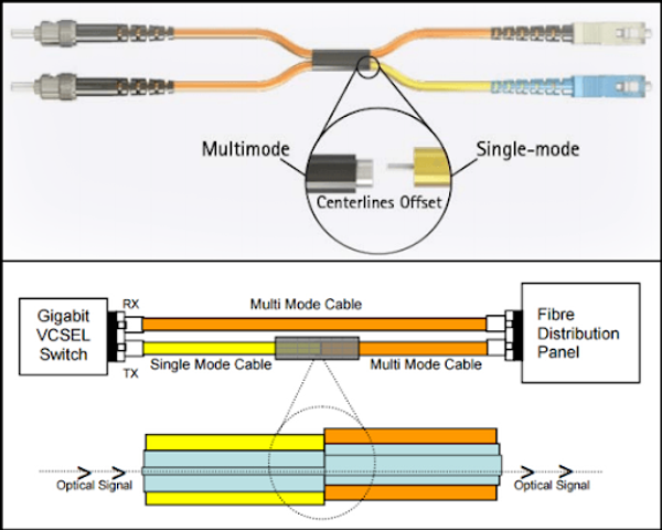
• Mode-conditioning LC Fiber Patch Cable — These hybrid jumpers combine single-mode and multimode fiber with a calibrated offset to prevent differential mode delay on legacy multimode plants. They let 1G/10G optics operate reliably over older infrastructure without wholesale recabling, typically available in LC-to-LC and LC-to-other connector formats.
• Breakout / fan-out LC Fiber Patch Cable — Breakout assemblies carry multiple individually jacketed fibers inside a common outer jacket (2–24 fibers) and convert from a high-density trunk (MTP®/MPO) to individual LC connectors. They are a standard method for decomposing parallel high-speed links into duplex LC ports for server or switch connectivity.

LC adapters and patch panels
Good connectivity is as much about mechanics and organization as it is about optics.
• LC adapters — Precision couplers that align two LC ferrules, typically designed to fit common patch-panel thicknesses (about 1.55–1.75 mm). They are available in simplex and duplex versions and may include shutters or dust protection for customer-facing installations.
• Patch panels — Rack-mounted distribution panels (1U, 2U, etc.) organize LC ports and make maintenance predictable. Thanks to LC’s small footprint, panels can scale from a few dozen ports to well over a hundred in ultra-dense designs. Panels are offered pre-loaded with adapters or empty for custom configurations; choose layouts that balance density with technician access and cable management.

LC attenuator solutions
Attenuators manage optical power where receivers risk saturation or where power balancing is required in amplified systems.
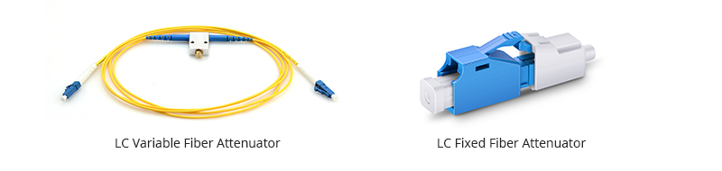
• Fixed attenuators — Provide a set attenuation (for example 1 dB, 3 dB, 5 dB) and are used for stable, repeatable power control.
• Variable attenuators — Allow fine tuning during commissioning and testing.
• Interface considerations — Attenuators are manufactured for UPC or APC ferrules; APC variants should be used where low back-reflection is a system requirement.
Other LC-interface assemblies and hybrid options
LC is not an island—its ubiquity makes it the natural endpoint for many active and modular devices.
• MTP®/MPO to LC cassettes — These pre-terminated modules convert high-density MPO trunks at the rear into rows of LC ports on the front, simplifying moves, adds and changes in data-center topologies.
• Transceiver modules — Duplex LC remains the standard interface for many pluggable optics (SFP, SFP+, SFP28, and in breakout applications for QSFP-class modules). Correct jumper selection (mode, polish type and connector quality) is essential when mating to optics.
• Media converters — Whether bridging copper to fiber or linking multimode and single-mode segments, many media converters expose LC ports for direct attachment to the fiber plant.
Conclusion
LC’s success is simple: it delivers the density of a small form factor without abandoning the repeatability and performance engineers depend on. When you design or operate LC-based links, the three practical disciplines that pay off are: (1) specify the correct polish and mode for the application, (2) standardize cable types, lengths, and color/polarity conventions, and (3) inspect and test every termination so you catch dirt, scratches, and mis-matings before they become outages. These modest rules keep LC networks reliable and maintainable across the messy realities of real-world racks and closets.