
A well-built fiber link rarely fails, but when it does the symptoms can be short, confusing, and expensive to chase. This guide lists the actual, field-proven problems technicians encounter most often and gives step-by-step troubleshooting actions you can copy into your maintenance routine. Keep this article tightly focused on practical fixes — no speculation, no unrelated background — so you can resolve faults and get links back to full performance quickly.

Why follow a strict sequence
Good troubleshooting is a sequence, not a scattershot of tests. Start with the simplest, fastest checks (visual inspection, cleaning, cable routing) and only move to instrumentation (power meter, VFL, OTDR) when those steps don’t clear the fault. This saves time and prevents needless part swaps.
1 — Contaminated connector end-faces (the biggest single cause)
Symptom: intermittent errors, high insertion loss, or a noisy link that sometimes clears after unplugging and re-plugging. The most common field failure is contamination on connector ferrules — dust, oil from fingerprints, and deposits from cleaning wipes that weren’t lint-free all raise insertion loss and reflectance. The fastest cure is inspection with a fiber microscope and the standard inspect → clean → inspect → mate workflow. Use approved lint-free wipes, specialty cleaning pens or cassette cleaners, and re-test after cleaning. In many surveys and manufacturer guides, contamination is cited as the leading cause of field failures; a disciplined end-face routine prevents most repeat service calls.
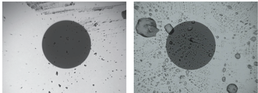
How to troubleshoot: always inspect end-faces before replacing modules or cabling. If cleaning improves loss by a few tenths of a dB and stabilizes the link, the problem was contamination.
2 — Bend radius violations (macrobends and microbends)
Symptom: wavelength-dependent loss (often worse at longer wavelengths), loss that spikes when a cable is flexed or moved, or visible tight loops and kinks at routing points. When a fiber is bent past its rated bend radius, light leaks from the core and attenuation rises; this loss is a function of bend radius, number of bends and signal wavelength. Modern bend-insensitive fibers exist, but correct routing is still essential. Re-route to respect the manufacturer’s minimum bend radius, replace damaged jumper(s), and add bend protectors at tight entry points.
How to troubleshoot: gently flex suspect segments while watching a power meter or OTDR; loss that grows during flexing indicates bend-related attenuation.
3 — Poor splices and connectorization
Symptom: discrete loss events on an OTDR trace, step increases in end-to-end loss, or a single connector/splice that degrades link performance. Factory fusion splices are typically very low loss; poor field fusion technique or mechanical splices can introduce higher loss. Use splice carts or a skilled fusion operator for permanent repairs; replace mechanical splices in high-reliability links. For accurate acceptance and troubleshooting, combine OLTS insertion-loss testing with OTDR traces and, where loss numbers matter, perform bi-directional OTDR testing and average the results.
How to troubleshoot: run an OLTS pass/fail insertion loss test to confirm overall compliance, then use OTDR to localize the event and decide whether to re-splice or replace.
4 — Physical damage (cuts, crushes, rodent chew)
Symptom: total loss, visible sheath damage, or a sharp reflection/break on the OTDR trace. Physical faults are obvious when you can locate the jacket damage; less obvious when a cable is pinched in a door or crushed under weight. Short accessible runs often show the fault with a Visual Fault Locator (VFL), which uses visible red light to reveal breaks or tight bends; for buried or long runs the OTDR gives the distance-to-fault so you can dispatch a dig crew to the right spot. Replace or re-route damaged sections and improve mechanical protection at repeat failure points.
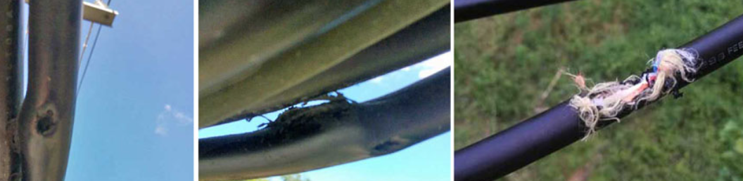
How to troubleshoot: use a VFL for quick continuity checks and an OTDR when distance location is required.
5 — Connector mismatch, poor mating, or wrong polish type
Symptom: unusual reflectance, higher-than-expected insertion loss after patching, or intermittent flakiness when patching panels. Mating UPC to APC, using the wrong adaptor, or poor ferrule flatness increases reflectance and insertion loss. Confirm connector types and polarities before mating; inspect and, if necessary, re-terminate suspect ports. Standards give practical loss allowances per connection — know the design budget and how many connection points are acceptable in your link.

How to troubleshoot: visually inspect polish types (APC angled vs UPC flat is visible) and measure return loss or insertion loss if reflectance is suspected.
6 — Link budget exceeded (design vs as-built)
Symptom: marginal signals that fail under load, or links that “pass” single tests but fail in operational conditions. If an installation was planned close to the optical loss budget, any extra connector or splice loss will push it over. Calculate end-to-end loss from cable length, connector and splice counts, and known component losses; verify with a light source + power meter (OLTS). If installed loss exceeds design, reduce connection points, rework poor splices, or use optics with better sensitivity.
How to troubleshoot: measure absolute insertion loss with a calibrated source and power meter and compare to the allowed budget.
Field pro tips that save repeat visits
• Inspect before you replace — cleaning often fixes what looks like a major fault.
• Label and document every test: OTP traces, OLTS numbers, and connector IDs reduce guesswork on subsequent visits.
• Use proper strain relief, avoid sharp tie wraps, and install bend-limiting hardware at tight routing points.
• When in doubt about a splice or connector, rework it with correct tools rather than adding another patch point.
Conclusion
When a link fails, follow this escalation: inspect and clean connectors → check continuity with a VFL → measure end-to-end loss with an OLTS → locate events with an OTDR (bi-directional when accuracy matters) → repair or replace the faulty component. Most real-world faults are prevented or fixed by neat cable management, clean end-faces and a disciplined, documented test workflow. Stick to that sequence and you’ll resolve the majority of common fiber troubles quickly and with confidence.