
Accurately testing an optical Transceiver means proving two things: that the module is emitting the right power at the right wavelength, and that the link it’s attached to delivers that signal without unexpected loss or reflections. In practice you’ll use two complementary tools — an optical power meter (with a stable light source or the transceiver’s own transmitter) to measure absolute power and end-to-end loss, and an OTDR to locate events, splices and reflectance along the fiber. This guide walks a practical, field-ready workflow and explains the settings and test artifacts technicians routinely check.

What you need and preliminary checks
-
Optical power meter and calibrated reference source (or a meter that can be zeroed against a known source). Always confirm the meter is calibrated and set to the transceiver’s wavelength (e.g., 850 nm, 1310 nm, 1550 nm).
-
OTDR and an appropriate launch (and receive) cable or launch box sized for the OTDR’s dead-zone at your chosen pulse width. A launch cable lets the OTDR recover from its initial pulse and correctly show events near the transceiver.
-
Clean, inspected connectors and short, known-good test jumpers (reference test jumpers). Dirty end-faces are the most common cause of confusing or bad readings — clean and inspect before you test.
Step 1 — Measure the transceiver transmit power
-
Power up the transceiver in the host device and let it stabilize per the vendor’s warm-up time.
-
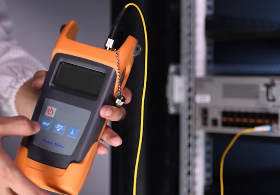
Set the power meter to the transceiver’s operating wavelength and attach a short, clean jumper from the transceiver output to the meter. Use the meter in dBm (absolute power) mode.
-
Record the displayed Tx power and compare directly to the transceiver datasheet (don’t guess acceptable levels). If your meter supports data logging, save the reading and the timestamp. This simple test tells you whether the module is producing output within its specified range.
Tip: If the transceiver offers a DOM/diagnostic register that reports transmit power, use that as a cross-check, but always trust a calibrated power meter for absolute verification.
Step 2 — End-to-end loss measurement with a source + power meter
If you need to certify or calculate link loss, perform a reference measurement and then the loss test:
-
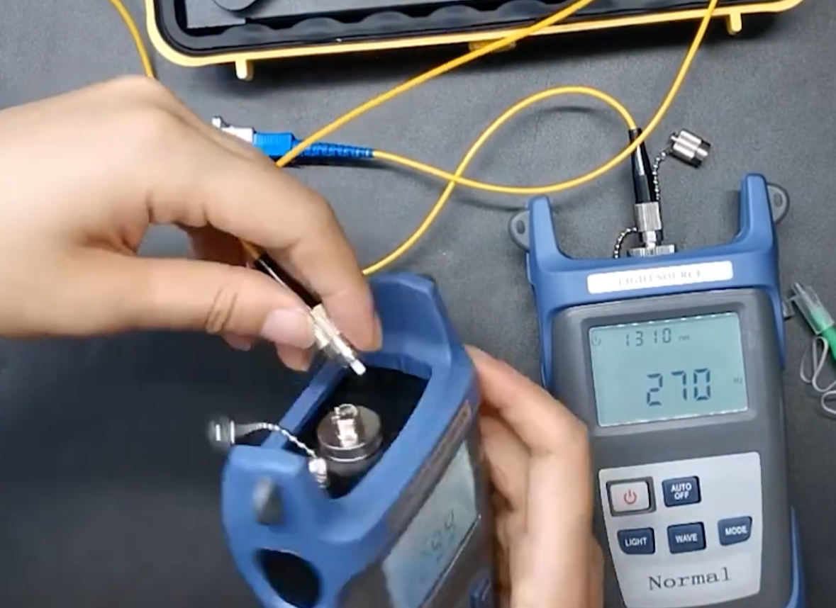
Using a stable reference light source (or the transceiver if that’s your source), establish a reference power: connect the source directly to the meter with a short, clean reference jumper and record reference power at the chosen wavelength.
-
Connect the source to the far end of the live link under test and measure power at the near end (or vice versa for transmit/receive roles). The difference between the reference and the measured power is link loss in dB.
-
Compare measured loss to the expected budget (cable type, connectors, splices). If loss exceeds budget, isolate with OTDR (next section).
Important: Standards (TIA/ISO) generally require OLTS (light source + power meter) tests for Tier-1 insertion-loss certification; use OTDR for troubleshooting and event location rather than as the sole certification report.

Step 3 — Use the OTDR to locate faults and verify link structure
An OTDR shows backscatter and reflections along the fiber length so you can confirm splice loss, connector reflectance and fiber length.
-
Connect an OTDR to the link using a launch cable/box. The launch cable allows the OTDR to display the very first connector and events that would otherwise fall in the instrument’s dead zone. Choose launch length based on your OTDR and pulse width — long singlemode tests often use hundreds of meters to a kilometer of launch.
-
Select a pulse width that balances range and resolution: shorter pulses yield finer event resolution (better for short links and connector events); longer pulses provide more dynamic range for long spans. The OTDR’s pulse width and range settings directly affect its event dead zones and ability to resolve close events.
-
Verify the group index/refractive index and test wavelength match the cable type — incorrect index produces erroneous distance readings. Run the trace and examine event markers for connector reflections (high reflectance), splice loss, and any unexpected attenuation slopes.
Interpreting results — what to look for
-
Transmit power outside datasheet limits: replace or investigate the module. Use power meter reading and DOM to cross-check.
-
Excessive end-to-end loss: compare against the expected budget; if the loss is high, OTDR will show whether the loss is distributed (fiber attenuation) or localized (bad connector/splice).
-
High reflectance at connectors: can cause receiver sensitivity issues; re-clean or replace suspect connectors. OTDR reflectance spikes point to reflective connectors or mismatched ferrules.
OTDR Event Table Reference
|
Event Type |
OTDR Trace Signature |
Typical Source |
Example Value |
|---|---|---|---|
|
Reflective Event |
Upward spike |
Connector, break, mismatch |
Reflection >–35 dB |
|
Non-Reflective |
Drop, no spike |
Splice, bend, microbend |
Loss: 0.05–0.5 dB |
|
Gainer |
Apparent signal gain |
Fiber mismatch |
Signal increase |
|
End-of-fiber |
Large spike, then flat |
Fiber end |
Reflection, then drop |
Safety and calibration notes
-
Never look directly into fiber ends — invisible laser light can damage eyes. Always treat fibers as potentially hazardous.
-
Use only calibrated meters and traceable references when reporting absolute power; poor calibration is a frequent source of conflicting results. Maintain device calibration records if you provide test reports.

WOLON offers a full range of optical transceivers and test-grade patching solutions designed for reliable deployment and straightforward field verification. Our transceivers are shipped with datasheets that list transmit power, wavelength and receiver sensitivity so you can quickly compare field power-meter readings to specification. For technicians who demand traceable performance, WOLON provides OEM-grade SFP, SFP+, QSFP and DWDM modules, plus certified test jumpers and launch-boxes to speed validation and minimize rework.