Accurate, efficient fault-finding and acceptance testing depend on picking the right tool for the job. This guide compares three core instruments — the OTDR (Optical Time Domain Reflectometer), the optical power meter (used with a light source), and the Visual Fault Locator (VFL) — so you can choose the right method and combine them in a professional workflow. The comparison focuses only on what the title promises: purpose, strengths, limitations, and practical tips for field use.
Quick overview: purpose of each tool
-
OTDR — a trace instrument that sends short light pulses into the fiber and measures backscattered and reflected light to produce a distance-based trace. It locates and characterizes events (splices, connectors, breaks), and estimates loss and reflectance along the link.
-
Optical power meter + light source — a two-instrument, end-to-end test used to measure absolute optical power and calculate insertion loss (dB) between two endpoints; this is the accepted method for loss certification because it directly measures the received power.
-
Visual Fault Locator (VFL) — a visible-red laser (around 650 nm) that makes physical breaks, macrobends and bad connectors “glow” so technicians can visually find damage and verify continuity over short spans.
(For clarity: this article uses the phrase fiber optic testing sparingly to stay focused on practical differences.)
How they work — practical, field-oriented descriptions
OTDR
An OTDR launches short pulses of infrared light into the fiber and times and measures the light that is scattered or reflected back. The returned signal is plotted as a trace (optical power vs. distance), which shows events (peaks for reflections, steps for loss). Because it is distance-resolved, an OTDR is indispensable for locating faults that are not at the fiber ends. Typical OTDRs offer selectable wavelengths (e.g., 1310 nm and 1550 nm) and a specification called dynamic range that governs how far and how sensitively the instrument can see. As a rule of thumb, choose an OTDR whose dynamic range is about 5–8 dB higher than the loss you expect on the link; singlemode units commonly advertise 35–45 dB ranges for medium to long spans.
Power meter + light source
A calibrated light source injects a steady optical signal at a chosen wavelength; a power meter at the far end measures the received power in dBm. By referencing (zeroing) with the reference test lead, technicians compute one-way insertion loss (in dB) directly. This method does not provide a distance trace, but it gives precise insertion loss and is the standard for acceptance tests and certification because it measures end-to-end loss under known conditions and wavelengths (e.g., 850/1300 nm for multimode, 1310/1550/1625 nm for singlemode).
Visual Fault Locator (VFL)
A VFL emits visible red light (typically 650 nm) that escapes the fiber at mechanical defects — you can literally see the jacket light up where the core leaks. VFLs are portable, fast, and inexpensive; they are ideal for campus/backbone troubleshooting, patch-panel tracing, connector identification and locating macrobends or breaks near the surface. They are not suited to certify loss or to locate very small or deep attenuation events beyond the VFL’s practical visibility range. Modern VFL units come in 1 mW to 5 mW output options and often include adapters for LC/SC connectors.
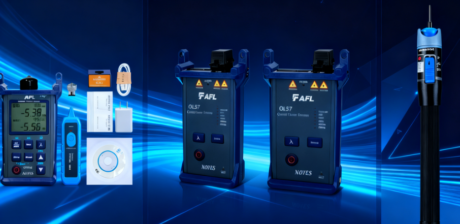
When to use which tool — simple decision rules
-
Use a power meter + light source when: you need accurate end-to-end loss numbers for acceptance testing, certification, or SLA sign-off. This is the “go/no-go” check for link loss and is required by most cabling standards for pass/fail.
-
Use an OTDR when: you need to locate and characterize faults by distance (where is the break? how much loss at this splice? which connector is reflective?). OTDRs are the right choice for troubleshooting buried cables, long spans, and when a map of events along the fibre is necessary. Choose dynamic range, pulse width and dead-zone parameters that match the fiber length and event density.
-
Use a VFL when: you want a quick visual check — trace a fiber through patch panels, find a break or tight bend close to the surface, or identify a mispatched fiber. It’s fast, cheap, and technician-friendly, but not a substitute for loss measurement or distance-resolved troubleshooting.
Strengths and limitations
-
OTDR strengths: distance resolution, fault location, event characterization.
Limitations: ambiguous loss numbers for short links without launch/receive (requires launch/receive reference cables), interpretation skill required, and limited absolute-loss accuracy compared to a power-meter method. -
Power meter strengths: precise power and loss numbers, simple to interpret, standard for certification.
Limitations: no information on where loss occurs; does not locate faults by distance. -
VFL strengths: immediate, visual identification of breaks, bends and mispatches; cheap and fast.
Limitations: visible laser cannot travel indefinitely—useful for short/medium spans and surface-accessible faults only; never use VFL on fibers that may carry live traffic unless expressly safe.

Recommended field workflow
-
Continuity & tracing: start with a VFL to identify the fiber and find obvious breaks or bends.
-
Acceptance loss test: perform power-meter + light source measurements at required wavelengths to certify insertion loss.
-
Detailed troubleshooting: if loss or failure is found, use an OTDR (with appropriate launch/receive cables) to locate and characterize the fault and measure distance to the event.
Practical tips (field-hardened)
-
Always use a launch (pulse) cable for OTDR testing to characterize the first connector and remove the OTDR dead-zone ambiguity.
-
For loss testing with power meters, always set and save a reference with your test cords to avoid systematic errors.
-
Use the correct test wavelengths for the fiber type (850/1300 nm for multimode; 1310/1490/1550/1625 nm for singlemode, as required).
-
Don’t use a VFL on fibers that may be carrying active optical traffic at the same time — visible lasers and live systems can create hazards and inaccurate results.
For installers and network engineers seeking reliable fiber cable and test-ready assemblies, WOLON’s fiber cable series offers factory-terminated patch cords, MPO/MTP trunks, and armored outdoor/duct cable options made to industry standards. WOLON cables are manufactured to tight attenuation and geometric tolerances, simplifying acceptance testing with power meter methods and ensuring predictable OTDR traces during troubleshooting. Contact WOLON for custom jacket types, pre-terminated lengths and test documentation to speed deployment and reduce field rework.