Direct-attach copper (DAC) assemblies are widely used for short-reach links inside racks and across adjacent racks because they’re low-cost, low-latency, and power-efficient. But their electrical nature means installers must validate signal integrity and run bit-error-rate tests before deployment. This article explains, in practical detail, how to test Dac Cable end-to-end, what measurements matter, and the acceptance criteria that reliably separate “good” from “bad.”
What you must test
Testing DAC cable performance focuses on two complementary domains:
-
Signal-integrity (SI) measurements — insertion loss, return loss/reflection, crosstalk and eye-diagram characteristics — to confirm the channel’s analog behavior.
-
Digital performance (BER) — long-duration bit-error-rate tests using industry patterns (PRBS) to prove the link meets the target error rate under real-data conditions.
Both are needed: SI finds margin issues quickly; BER proves the link can carry real packets without data corruption.
Test preparation & equipment
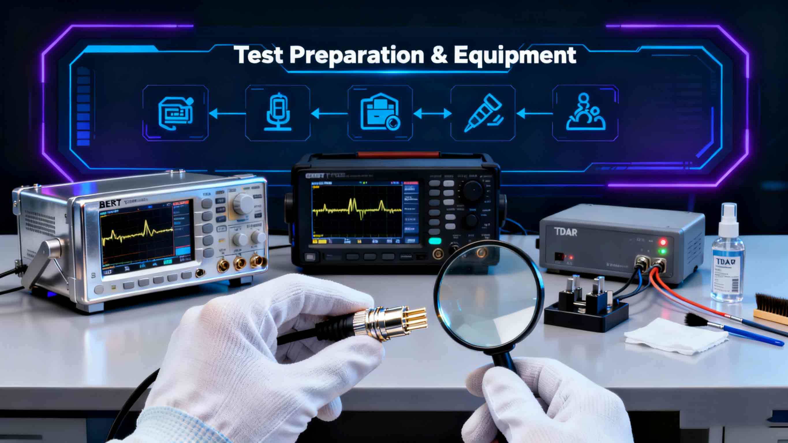
Typical test gear for DAC validation includes a dual-port BERT (bit-error-rate tester) or a handheld data center cable tester with cable test scripts, a high-bandwidth oscilloscope/serial-data analyzer for eye diagrams, and optionally a TDR if you suspect discontinuities. Common, field-proven platforms are VIAVI’s T-BERD/MTS family and OneAdvisor series, which provide combined BERT + cable test scripts for SFP+/QSFP-class DACs.
Before you begin: visually inspect connectors for damage, verify part numbers and pinouts, and ensure both ends are clean and fully seated. Use matched test transceivers or tester ports that mimic the host PHY to avoid misleading results.
Signal-integrity checks
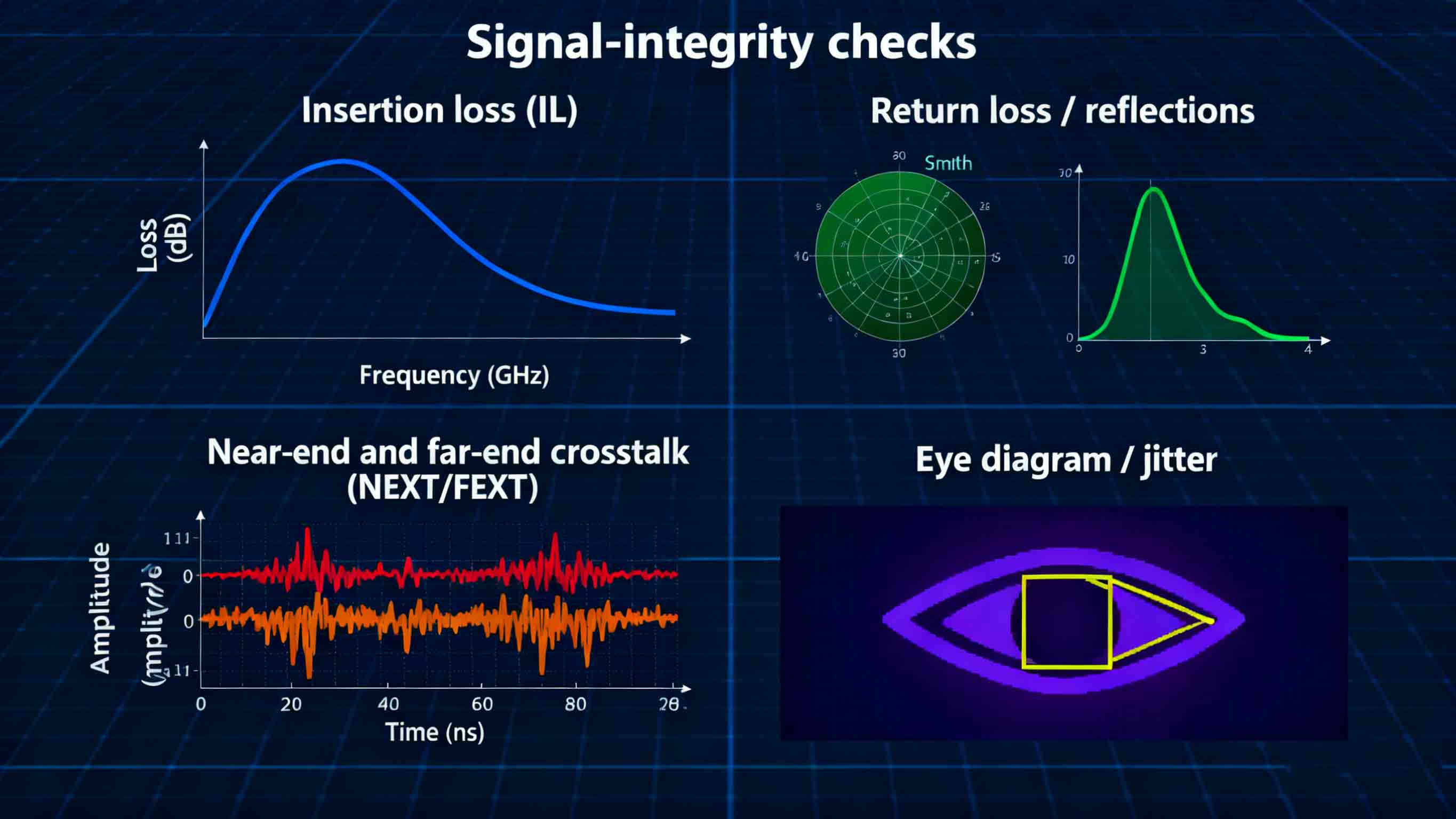
Signal-integrity testing is an analog health check that reveals loss and distortion which will reduce eye opening and raise BER.
-
Insertion loss (IL): measure attenuation vs frequency across the channel. Excessive IL at the signaling bandwidth shrinks the eye and is a common failure mode in long or poorly manufactured copper assemblies.
-
Return loss / reflections: impedance mismatches at connectors create reflections that close the eye and can produce intersymbol interference (ISI).
-
Near-end and far-end crosstalk (NEXT/FEXT): important for breakout or multi-pair ribbon assemblies.
-
Eye diagram / jitter: capture a serial eye at the intended data rate to quantify total jitter (TJ) and signal-to-noise. Oscilloscope measurements give a visual pass/fail and provide numeric margin against the standard’s receiver sensitivity.
Standards and vendor application notes describe the required masks and thresholds for specific form factors (for example, SFP+ direct-attach test methods are defined in SFF-8431). Use those masks when available.
BER testing: patterns, duration, and pre-FEC vs post-FEC
A bit-error-rate test is the ultimate functional proof. Typical methodology:
-
Choose test patterns: PRBS-7, PRBS-15, PRBS-31 (or vendor-required patterns) — some patterns stress different aspects of channel equalization and are standard for qualification.
-
Run long-duration tests: short runs can miss intermittent errors. For production qualification, run continuous tests for hours; installers commonly run shorter acceptance runs (e.g., 15–60 minutes) that still provide useful confidence in the field.
-
Pre-FEC vs post-FEC reporting: with modern high-speed links (e.g., 200G/400G), forward-error-correction (FEC) may correct many bit errors. For acceptance you should report both pre-FEC BER (raw channel performance) and post-FEC BER (what the link will actually deliver). Engineers often require pre-FEC performance to stay below a threshold that assures long-term stability while post-FEC must meet the service-level BER target. VIAVI and industry guidance emphasize measuring both.
Common acceptance targets
For classic 10-Gigabit Ethernet DAC interoperability testing, interoperability programs reported a 1×10⁻¹² BER target during plug-fest testing. Newer higher-rate channels often specify different pass/fail numbers and rely on FEC to reach service goals; always use the standard or system design target for the speed you’re testing.
concise step-by-step test procedure
This checklist gives a field workflow for how to test DAC cable quickly and reproducibly:
-
Pre-check: inspect connectors, confirm part numbers, and set tester ports to match the intended host transceiver speeds.
-
SI spot checks: measure insertion loss and return loss across the expected bandwidth; capture an eye diagram at nominal data rate and compare numeric margins to the published mask (or vendor spec).
-
BER test setup: connect both ends to the BERT (or loop back one end and use a host-side tester as a receiver), select PRBS patterns, set the data rate and pre-emphasis if applicable.
-
Run BER: choose a runtime consistent with risk tolerance — field acceptance runs of 15–60 minutes are common; lab qualifications use multi-hour or 24-hour runs. Record pre-FEC and post-FEC BER and any alarm events.
-
Document & compare: save reports (eye, IL, BER logs). If results fail, perform a continuity check and TDR/localize the fault before replacement.
Troubleshooting common failures
-
Closed eye / high jitter: check for excessive insertion loss, bad connectors, or incorrect host equalization settings. Use a scope to identify whether noise or ISI dominates.
-
Intermittent BER spikes: examine mechanical retention, thermal expansion, and connector cleanliness. Reproducing errors during temperature cycling or bending often reveals marginal assemblies.
-
Pass post-FEC but fail pre-FEC margins: acceptable for some deployments, but note that any future degradation (aging, movement, higher noise) can overwhelm FEC margin—prefer components that show comfortable pre-FEC margin during qualification.
Acceptance criteria
Acceptance must be defined before testing. A practical acceptance rule set used by many teams:
-
Visual + mechanical pass (no damage, correct part).
-
SI numeric pass: IL and return-loss within the form-factor or manufacturer’s limits (or within the system budget).
-
BER pass: no bit errors observed during the agreed acceptance run OR pre-FEC BER better than the predefined threshold (for 10GbE historical target ≈ 1E-12 during formal tests; consult the standard for your speed). Always record pre- and post-FEC.
Conclusion
Testing DAC cables requires both analog and digital validation: signal-integrity checks expose margin problems, while rigorous BER testing proves the link’s functional reliability in service. For field work, use a handheld cable tester or BERT with the proper cable scripts, document pre-FEC and post-FEC BER, and adopt clear acceptance criteria tied to the speed and standard in use. A consistent testing routine prevents costly troubleshooting and avoids deploying marginal assemblies into production. If you follow these steps, you’ll know exactly how to test DAC cable and when a DAC cable truly passes your acceptance gate.