Overview of Single-Mode and Multi-Mode Compatibility
Single-mode (SMF) and multi-mode fiber (MMF) use different core sizes, sources and wavelengths. These differences determine which transceivers work with which fiber and how far signals can travel. Understanding the compatibility constraints prevents costly downtime and troubleshooting.
Key Compatibility Factors
-
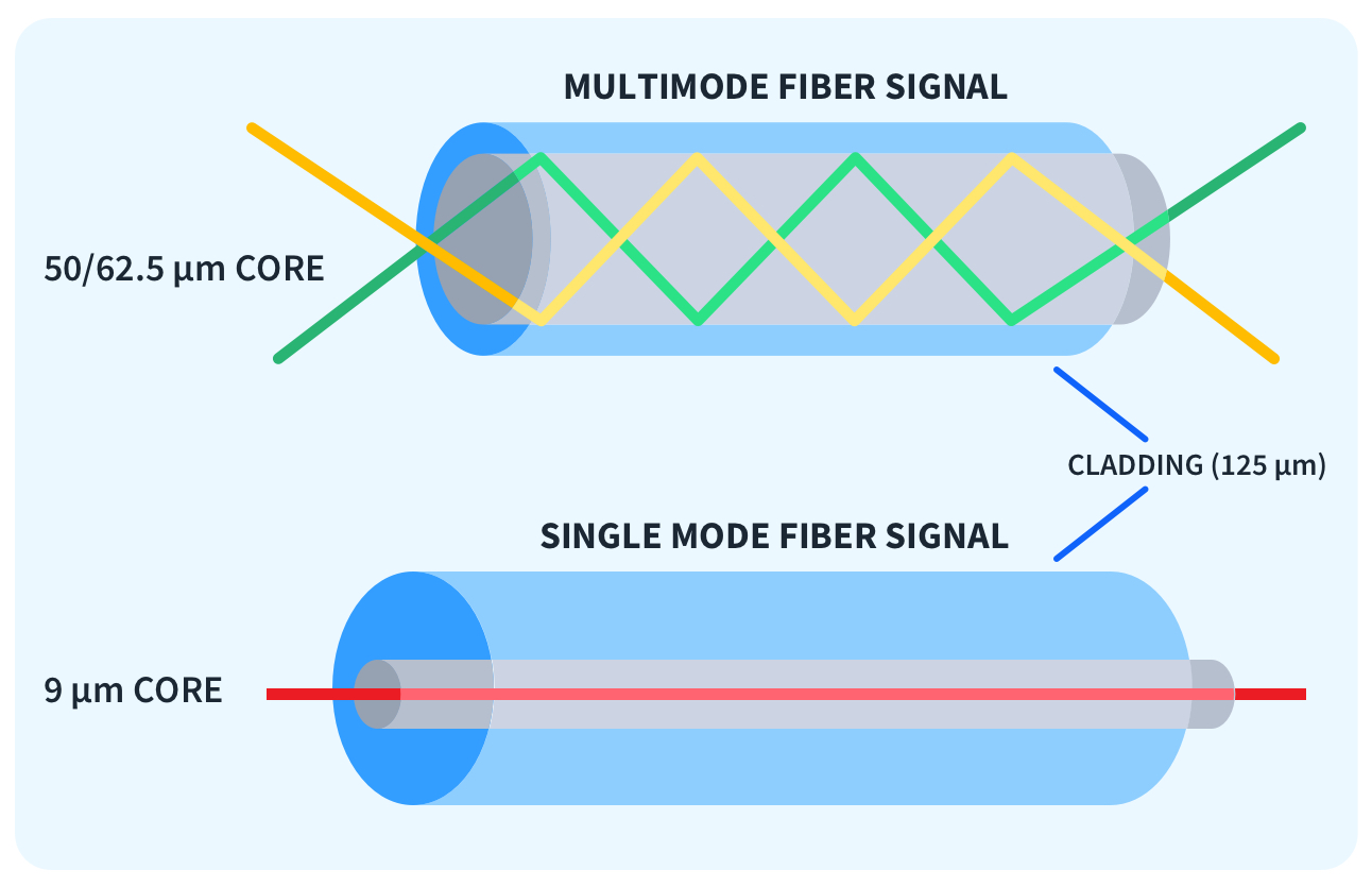
Single-mode fiber has a narrow core (8–10 µm). It’s built for long-distance data transmission. It can cover distances from 2 km up to 200 km. This fiber operates at 1310nm, 1490nm, or 1550nm wavelengths. You’ll find it in metro, campus, and backbone networks. Single-mode transceivers come in blue, yellow, green, or purple colors.
-
Multi-mode fiber has a larger core (50 µm or 62.5 µm). It works best for short distances. Think data centers or LANs. It operates at 850nm or 1300nm wavelengths. Multi-mode supports transmission distances from 100 m to 550 m. Some fibers can reach up to 2 km. Multi-mode SFPs are marked with black.
Compatibility Matrix: Supported Configurations
|
transceiver Type |
Fiber Type |
Typical Use |
Max Transmission Distance |
|---|---|---|---|
|
Single-mode SFP |
Single-mode |
Long-distance links |
2–200 km |
|
Single-mode SFP |
Multi-mode |
Emergency short connections |
≤100 m (signal issues) |
|
Multi-mode SFP |
Multi-mode |
Short-distance networks |
100–550 m (up to 2 km) |
|
Multi-mode SFP |
Single-mode |
Not recommended |
Severe loss; unreliable |
Technical Differences Impacting Compatibility
Light Source: Multi-mode SFPs use LEDs or VCSELs for light with a broad beam. Single-mode SFPs use laser diodes for a narrow, focused beam.
connector types: Single-mode uses LC connectors. Multi-mode may use SC, LC, or MPO connectors. It depends on your system setup.
Signal Transmission: Single-mode fiber transmits light in a single path. This keeps signal loss and dispersion low for longer distances. Multi-mode fiber disperses light in multiple paths. This increases the risk of signal weakening and errors over long distances.
Real-World Compatibility: Test Cases and Performance Data
-
I’ve seen people use a single-mode SFP with a multi-mode patch cable (like 100m OM3). It can create a basic link. But expect power loss, CRC errors, and unstable connectivity. Use this setup for temporary, non-critical situations.
-
Connecting a multi-mode SFP to single-mode fiber creates a major signal mismatch. A small portion of the transmitted light gets captured. This leads to high attenuation and frequent link drops. I suggest you avoid such setups. Use them if essential and with proper mode conditioning cables.
Technical Reasons for Incompatibility
Mixing single-mode and multi-mode transceivers creates major optical and hardware problems. This leads to unreliable network performance. Here’s why:
-
Light source & beam profile: SM lasers are narrow and Coherent; they couple efficiently into a 9 µm core. MM VCSELs/LEDs produce a broader beam, designed for large cores.
-
Modal dispersion & DMD: MMF supports multiple propagation modes; differential mode delay (DMD) limits reach at higher data rates. SMF avoids modal dispersion, enabling higher bandwidth over long distances.
-
Optical budget & launch conditions: SMF systems expect narrow spectral width and tight alignment; MMF systems tolerate broader launch conditions but at the cost of limited distance.
Industry Warnings and Standard Practice
Network standards and equipment manuals are clear. Don’t mix single-mode and multi-mode transceivers or fiber. Their optical budgets, wavelengths, and expected distances don’t align. You can’t make them compatible by connecting cables.
Cost and Practical Connection Requirements
|
Feature / Limitation |
Single-Mode |
Multi-Mode |
|---|---|---|
|
Core Size |
9 µm |
50/62.5 µm |
|
Light Propagation |
Multiple modes |
|
|
Max Distance (typical) |
2 km – 40 km |
500 – 600 m |
|
Bandwidth |
Very high |
Limited by modal effects |
|
Modal Dispersion |
None |
Severe at distance |
|
Typical Transceiver Cost |
1.5 – 4x more expensive |
Lower |
|
Light Source |
Laser |
LED/VCSEL |
Example: For 100G networks, single-mode transceivers need two fibers (Tx/Rx). Multi-mode solutions often require eight fibers due to parallelization. This makes single-mode a different category. I see it as a different network architecture.
Compatibility Matrix: Mixing Single-Mode and Multi-Mode Transceivers
Pick the right transceivers and fiber types. This choice is key for stable network performance. Below is a practical compatibility matrix for deploying single-mode and multi-mode optical modules.
Fiber & Transceiver Compatibility Table
|
Transceiver Type |
Fiber Type |
Compatibility |
Max Transmission Distance |
Issues/Notes |
|---|---|---|---|---|
|
Single-mode |
Single-mode |
Compatible |
Up to 120 km |
Stable, all vendors recommend this; designed for metro, campus, backbone networks |
|
Multi-mode |
Multi-mode |
Compatible |
Up to 550 m |
Ideal for LAN, data center, and short-reach apps; lowest cost |
|
Single-mode |
Multi-mode |
Partial Compatibility |
~100 m (unstable) |
For emergency/temporary use; expect high power loss, CRC errors, link instability |
|
Multi-mode |
Single-mode |
Not Compatible |
None |
Light mismatch causes severe loss; connection fails most times; manufacturers don’t support this |
Distance and Standard References
|
Standard |
Transceiver Type |
Fiber Type |
Max Distance |
|---|---|---|---|
|
1000Base-SR |
Multi-mode |
OM2/OM3/OM4 |
550 m |
|
1000Base-LX |
Single-mode |
OS2 |
10 km |
|
1000Base-EX |
Single-mode |
OS2 |
40 km |
|
1000Base-ZX |
Single-mode |
OS2 |
80 km |
Directional Asymmetry in Compatibility
In optical networks, single-mode (SM) and multi-mode (MM) transceivers don’t work the same way in both directions. This is directional asymmetry.
Key Points on Directional Asymmetry
1.SM Transceivers Over MM Fiber:
Single-mode lasers work with a narrow 9μm fiber core.
If you plug a single-mode SFP into multi-mode fiber (50μm or 62.5μm core), the signal can travel a short distance. You might get link lights. But signal power drops fast. Reliability suffers.
Real-case scenario: Network engineers have connected SM transceivers over MM fiber for brief, emergency connections. The link comes up. But there are CRC errors, high attenuation, or sudden link drops.
The usable distance is limited. It’s often less than 100 meters. This happens even if the transceiver’s datasheet suggests many kilometers over SM cable.
2.MM Transceivers Over SM Fiber:
Multi-mode SFPs use LED or VCSEL sources. These spread light across the large core of MM fiber.
You connect these to SM fiber (with a tiny 9μm core). Almost all the light is lost. You might see a link light. But no real data transmission happens. Total signal loss is the reality.
Case example: An IT team using HP J9775A switches installed MM SFPs over a new 100m SM fiber link. The link never established. This shows that MM optics cannot function on SM cable.
Comparative Scenario Table
|
Configuration |
Link Status |
Usability |
|---|---|---|
|
Single-mode SFP over SM Fiber |
Yes |
Supported, reliable and high performance. |
|
Single-mode SFP over MM Fiber |
Maybe |
Works at very short distances. Unreliable results. |
|
Multi-mode SFP over SM Fiber |
No |
No real data. Link light may appear but unusable. |
|
Multi-mode SFP over MM Fiber |
Yes |
Supported. Best for short-range applications. |
Note: “SM SFP over MMF” may show a link. But performance is unpredictable. Not supported for production use.
Best Practices and Warnings
-
Always match transceiver type to fiber type. SMF↔SMF, MMF↔MMF.
-
For unavoidable mixing: use media converters or mode-conditioning patch cords (MCPs) and validate with lab tests.
-
Avoid mixed links in critical backbones or data center cores. If upgrading, standardize on SMF for future scalability.
-
Labeling & documentation: mark fiber type, connector, and transceiver part numbers at both ends.
Summary of Key Takeaways
-
Match fiber type to transceiver type for production links. Mixing is a short-term workaround only.
-
Test thoroughly using wavelength-aware tools. Link LED ≠ link health.
-
For scalability, standardize on single-mode for core/backbone and use media converters or MCPs only when unavoidable.
Summary:
For network stability and support, pair single-mode optics with single-mode fiber. Pair multi-mode optics with multi-mode fiber. I suggest using bridging technologies when you have no other choice. Understand their capabilities and limits before you commit.