Choosing the correct conversion cables and modules for an MTP/MPO-to-LC transition requires a focused, methodical approach. This article answers How To Choose Conversion Cables And Modules with precise, actionable criteria: connector family and quality, fiber type and performance, polarity and pinning, end-face geometry, insertion-loss expectations, and mechanical/installation details. Follow these steps in order and you will select assemblies that work on the first try.
Confirm connector family and required performance
First, identify whether the multi-fiber connectors in your network are standard MPO or branded MTP®. MTP® is a high-performance implementation of the MPO form factor; it is engineered to tighter mechanical and optical tolerances and typically yields more consistent insertion loss. When you specify conversion assemblies, match the connector family to the system expectation (or choose validated MTP®-class assemblies for critical links).
Choose the correct conversion form factor (fan-out vs cassette/module)
Decide whether you need a direct fan-out (breakout) cable or a cassette/module installed in a panel:
-
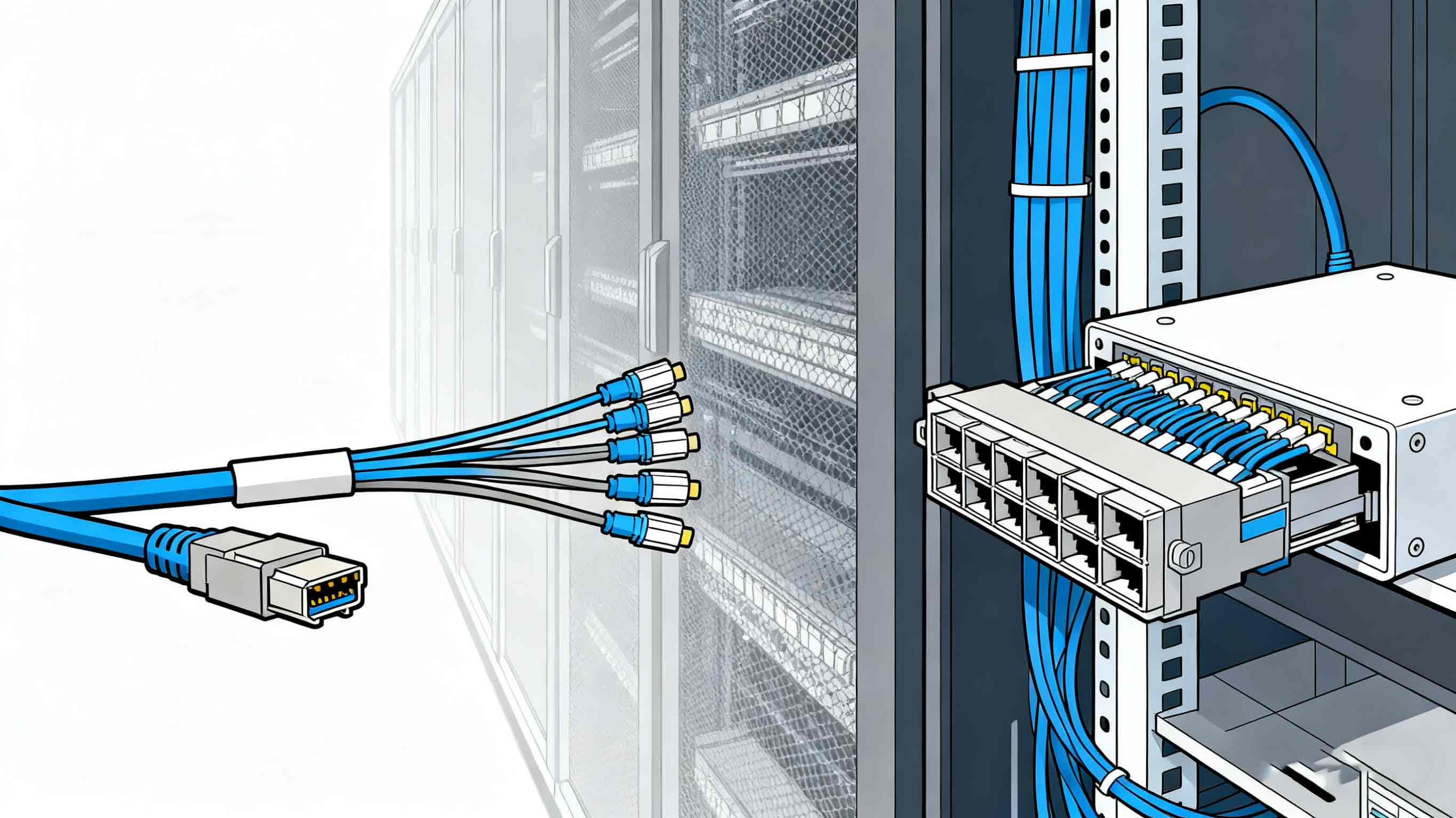
Fan-out (MPO-to-LC breakout) cables: the MPO/MTP connector on one end splits into multiple duplex LC leads. Use these when a continuous, compact assembly from trunk to equipment is required and when field density is moderate.
-
MPO-to-LC cassettes / modules: factory-assembled modules that accept an MPO trunk at the rear and present LC ports at the front. Use cassettes for high-density racks and structured cabling because they centralize polarity handling and simplify moves, adds, and changes.
Select fan-outs for simple point connections; select cassettes for scalable, serviceable patching architectures.
Match fiber type to application and transceiver requirements
Confirm the fiber type required by the active equipment and link distance:
-
Multimode (OM3 / OM4 / OM5) is typical inside data centers for short to medium parallel optics links. OM4 gives greater reach and margin versus OM3.
-
Singlemode (OS2) is required for single-fiber, long-reach optics and many long-distance or DWDM systems.
Never mix fiber grades within the same channel. Match the conversion assembly’s fiber type to the transceiver and trunk fiber. Verify the transceiver datasheets to confirm supported fiber types before ordering.
Verify polarity mapping and connector gender/pinning
Polarity ensures transmit and receive channels align after conversion. There are standard MPO polarity schemes (commonly referred to as Method A, B, and C or Type A/B/C). You must determine:
-
Which polarity method your system uses.
-
Whether the MPO/MTP ends must be pinned (male) or unpinned (female) to mate with existing trunks or ports.
-
How the chosen cassette or fan-out implements polarity (some cassettes are pre-wired to a method; some fan-outs rely on patch cord orientation).
Map Tx→Rx channel numbers on paper and confirm the selected conversion assembly matches that mapping. Polarity mistakes are the most frequent cause of non-functional conversions; document the mapping for every link and label both ends.
Specify end-face geometry (UPC vs APC) where applicable
Choose end-face polish according to optical requirements:
-
UPC (Ultra Physical Contact) is standard for most short-reach data center links.
-
APC (Angled Physical Contact) reduces back-reflection significantly and is used where low return loss is essential (certain singlemode systems).
Ensure all mated connectors in the channel have compatible geometries — APC and UPC are not compatible for direct mating. Specify the required polish for both the MPO/MTP end and the LC ends if singlemode links demand APC performance.
Set realistic insertion-loss expectations and request test data
very conversion adds insertion loss. When selecting assemblies:
-
request documented insertion-loss (IL) and return-loss (RL) specifications from the supplier for the specific part number.
-
Prefer assemblies with published IL that meet your link budget margins. Branded MTP® assemblies often show lower typical IL versus generic MPO assemblies; check published numbers.
-
Require factory test reports for shipment when working at high speeds (40G/100G/200G/400G) or when margins are tight.
Plan your link budget by summing the IL of trunk connectors, conversion modules, and patch cords, and leave margin for future moves. Test installed channels with an appropriate test method (IL/Loss test with light source/power meter or certification test equipment).
Confirm mechanical, environmental, and labeling details
Before finalizing an order, confirm these mechanical attributes:
Fiber count (8, 12, 24, etc.) matched to your transceivers and panel layout.
Cable jacket type (LSZH, PVC, Plenum) to meet building code and environmental needs.
Breakout/fan-out length to ensure proper routing without tight bends.
Bend radius and cable management features so connectors will not be stressed in racks or panels.
Connector cleaning and dust caps included or specified.
Clear labeling and polarity diagrams provided with assemblies for installation.
A well-specified mechanical package prevents field rework and makes polarity verification straightforward.
Decide on supplier verification and spares
Select suppliers who provide clear, verifiable documentation: datasheets specifying IL/RL, polarity wiring diagrams, and per-unit factory test reports when required. Keep a small number of labeled, pre-tested spare assemblies (fan-outs or cassettes) matching your chosen configurations to minimize downtime during replacements.
Conclusion
When you ask How To Choose Conversion Cables And Modules, follow this exact sequence: identify connector family and performance requirements, pick the correct conversion form factor (fan-out vs cassette), match fiber type and polish, verify polarity and pinning, require insertion-loss documentation and test reports, and validate mechanical requirements. Applying each of these checks in order removes ambiguity and yields conversion assemblies that function reliably on deployment.