
Against the explosive expansion of AI compute clusters (H100/B200), 800G/1.6T ultra-high-speed optical networks and large-scale cloud data centers, fiber cabling density and deployment complexity have grown exponentially. During engineering rollout and procurement, misclassification of MPO/MTP Trunk Cables, Breakout/Harness Fanout Cables and Conversion Cables frequently triggers severe onsite failures: messy rack routing, excessive insertion loss, polarity mismatches, and permanent damage to MT ferrules. This guide systematically defines the core categories of MPO/MTP fiber assemblies, covering mechanical construction, polarity & gender mating rules, hierarchical deployment architectures and actionable troubleshooting best practices.
1. Core Definition & Fundamental Distinction of Three MPO/MTP Cable Categories
Per ANSI/TIA-568.3-D and IEC 61754-7 structured cabling standards, MPO/MTP fiber assemblies are categorized into three core families based on end connector form factors and their position within the end-to-end network topology:
MPO/MTP Physical Layer Cabling Hierarchy Overview
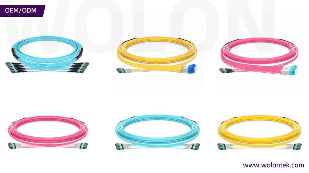
- Trunk Cable: Both ends terminated with identical fiber-count MPO/MTP connectors (e.g. 12F to 12F)
- Breakout / Harness Fanout Cable: One end MPO/MTP, the other end split into multiple single/duplex discrete connectors
- Conversion Cable: MPO/MTP connectors on both ends, with mismatched fiber counts or connector quantities on two sides
1.1 MPO/MTP Trunk Cable (Backbone Trunk Assemblies)
Definition: Pre-terminated fiber assemblies fitted with matching fiber-count MPO/MTP connectors on both terminals (8F↔8F, 12F↔12F, 24F↔24F, all standard female-to-female per global data center norms).
Core Function: Form the permanent fixed backbone of structured cabling systems, responsible for long-distance high-density signal transmission between cross-distribution areas (MDA to HDA, HDA to ZDA).
Engineering Attributes: Built with high-tensile strength outer jackets, micro-bundle or ribbon fiber structures. Every trunk assembly undergoes 100% factory pre-termination and 3D interferometer inspection. Designed for permanent fixed installation; frequent plugging/unplugging is strictly prohibited.
1.2 MPO/MTP Breakout / Harness Fanout Cable
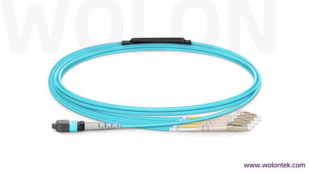
Definition: Single end terminated with high-density MPO/MTP connector; the opposite end splits via a dedicated furcation kit into multiple single-fiber or duplex connectors including LC, SC, SN, MDC and CS.
Industry Term Clarification:
- Breakout Cable: General umbrella term for all one-to-many split fiber assemblies
- Harness Cable: Short-length fanout assemblies dedicated to intra-rack patch connections between patch panels and active equipment
- Fanout Cable: Describes the physical design of individual single-fiber legs separated from the main cable bundleCore Function: Port splitting and heterogeneous equipment interconnection. Typical use case: converting one 400G DR4 MPO-12 Base-8 transceiver port into four independent 100G DR1 LC duplex server NIC links.
1.3 MPO/MTP Conversion Cable
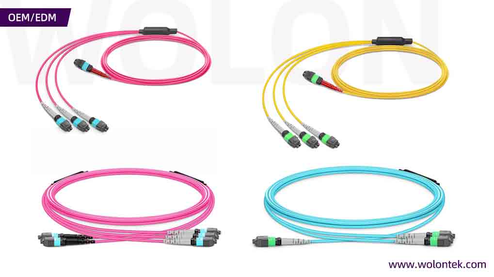
Definition: Dual-ended MPO/MTP assemblies with unmatched fiber counts or connector quantities on two sides.
Standard Configurations:
- 1×24F MPO split into 2×12F MPO
- 1×24F MPO split into 3×8F MPO
- 3×8F MPO converted to 2×12F MPOCore Functionality: Eliminate stranded dark fibers and resolve architecture incompatibility during network upgrades. For legacy facilities pre-wired with 12F/24F trunks migrating to Base-8 400G/800G parallel optics, conversion cables deliver 100% fiber utilization without full trunk replacement.
2. Full-Dimensional Technical Comparison Matrix
表格
| Evaluation Metric | Trunk Cable (Backbone Trunk) | Breakout / Harness Fanout Cable | Conversion Cable |
|---|---|---|---|
| Dual-End Connector Format | MPO/MTP both ends, identical fiber count | MPO/MTP on one end; LC/SC/SN/MDC discrete connectors on the other | MPO/MTP both ends, mismatched fiber count / connector quantity |
| Network Hierarchy Position | Backbone inter-distribution layer | Access & edge port splitting layer | Migration & architecture adaptation layer inside patch cabinets |
| Typical Deployment Scope | MDA ↔ HDA, HDA ↔ ZDA/EDA | HDA patch panel to EDA servers, TOR switch to GPU compute nodes | Rear side of cassette patch panels within HDA racks |
| Standard Fiber Count Frameworks | Base-8 (8/16/24/32F), Base-12 (12/24/48/72F) | 8F split to 4 duplex pairs; 12F split to 6 duplex pairs; 16F split to 8 duplex pairs | 24F to dual 12F, triple 8F to dual 12F and other mixed conversion specs |
| Mating Frequency | Extremely low (permanent fixed routing) | Medium frequency (equipment commissioning, port migration, daily maintenance) | Low frequency (permanently fixed inside patch panel systems) |
| Jacket & Tensile Performance | Thick reinforced jacket with Kevlar aramid yarn; armored & unarmored options available | Robust main cable body; thin individual 0.9/2.0/3.0mm legs post furcation | Compact micro-cable design optimized for dense rack cable management |
| Core Business Value | Cut field construction time and save over 70% rack routing space | Replace separate cassette modules and reduce end-to-end channel insertion loss | Preserve existing trunk infrastructure assets and achieve 100% fiber utilization |
3. Internal Mechanical Structure & Jacket Type Differences
Long-term reliability of fiber assemblies within dense data center environments relies on internal industrial design and mechanical construction.
Standard Breakout Cable Structure Layout
MPO/MTP Connector → Main Micro/Armored Cable Body → Molded/Metal Furcation Kit → Individual Fiber Legs → LC/SN Discrete Connectors
3.1 Cable Jacket Classification
- Micro-Cable: Outer diameter 2.0–3.0mm, embedded Kevlar tensile reinforcement, high flexibility. The primary jacket choice for MPO Trunk and Conversion cables.
- Ribbon Cable: Fibers arranged in flat ribbon arrays with ultra-high packing density, widely adopted for ultra-high-count trunks (48F+). Limited bending flexibility due to directional rigidity.
- Ruggedized Breakout Cable: Compression-resistant main jacket; each split leg wrapped in independent 2.0/3.0mm outer jackets to avoid single-fiber damage from external extrusion.
3.2 Critical Engineering Details of Furcation Kits
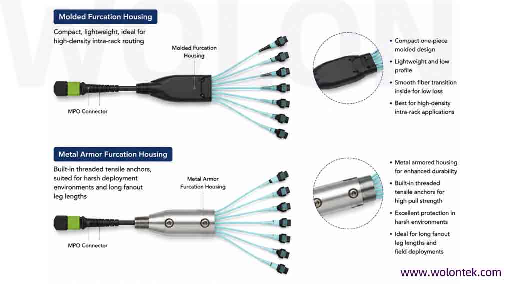
The furcation kit determines long-term breakout cable performance, serving as a protective metal/molded housing that safely separates bundled fibers and routes them to individual legs.
- Molded Furcation Housing: Compact, lightweight, ideal for high-density intra-rack routing
- Metal Armor Furcation Housing: Built-in threaded tensile anchors, suited for harsh deployment environments and long fanout leg lengths
3.3 Equal-Length vs Staggered-Length Fanout Legs
Fanout leg length specification directly impacts rack cable tidiness and minimum bend radius compliance during procurement:
- Equal-Length Legs: Matched for patch panels and flat adapter plate port arrays
- Staggered-Length Legs: Custom-designed for high-density fixed switches (Cisco Nexus, Arista 7000 series). Ports sit at incremental distances from cable management trays; staggered legs eliminate cable tangling and excessive tensile pull on far-end ports.
4. Mandatory Polarity & Connector Gender Mating Rules
Polarity Type A/B/C and male/female pin matching are the top root causes of link failures in MPO/MTP systems. Incorrect specification leads to total optical path disconnection or irreversible MT ferrule damage.
4.1 Non-Negotiable Gender Mating Iron Rule
- Male (Pinned): Connector front face equipped with two precision stainless steel guide pins
- Female (Unpinned): Connector with alignment holes only, no metal guide pinsAbsolute Mating Rule: Male connectors can only mate with female connectors.
- Male-to-Male mating: Collision of guide pins causes cracked ferrules and permanent connector failure
- Female-to-Female mating: Lack of mechanical alignment leads to core misalignment, channel insertion loss exceeding 10–20dB and complete signal loss
Default Gender Configuration of Common Hardware:
- Transceiver optical ports (400G/800G QSFP-DD/OSFP): Factory-built male pinned interfaces
- Patch cassette internal backside adapters: Typically male pinned
- Standard data center trunk cables: Industry recommended female-to-female, compatible with direct cassette/transceiver insertion
- Breakout cables for direct transceiver connection: MPO end must be female unpinned; breakout cables for patch panel interconnection require gender matching per panel backside hardware
Correct Direct Transceiver Interconnection Example:
800G DR4 Transceiver (Built-in Male Pinned Port) ↔ MPO-12 Breakout Cable (Female Unpinned MPO End) → Split LC Duplex Legs to GPU Server NICs
4.2 Polarity Type Application for Three Cable Families
Per ANSI/TIA-568.3-D, three standardized polarity mappings apply to all MPO/MTP assemblies:
- Trunk Cable Polarity Selection
- Type A (Straight-Through, Key-Up to Key-Down): 1:1 fiber position mapping. Requires Type-A adapters and cross-over patch cords to complete Tx/Rx lane reversal.
- Type B (Fully Flipped, Key-Up to Key-Up): Position 1 maps to position N, position 2 maps to N-1, universal standard for 400G/800G parallel optics (SR4/DR4/SR8). Supports direct end-to-end transceiver interconnection without extra cross-over jumpers.
- Type C (Pairwise Flipped, Key-Up to Key-Down): Adjacent fiber pairs reversed (1↔2, 3↔4). Exclusively for legacy duplex 10G/25G serial links; prohibited for all parallel 400G/800G transmission systems.
- Breakout Cable Polarity ImplementationFor parallel optical port splitting (e.g. 400G SR4 split to four 100G SFP+ links), breakout polarity must guarantee one-to-one Tx/Rx lane alignment. On Base-8 Type B breakout assemblies, MPO pins 1–4 (Tx lanes) automatically map to transmit cores of the first four duplex legs, while pins 9–12 reversed map to receive cores without manual reconfiguration.
5. Standardized Data Center Zoned Deployment Architecture
All MPO/MTP fiber assemblies must follow ANSI/TIA-942 structured cabling zoning logic for standardized deployment:
MDA (Main Distribution Area)
Recommended Product: High-fiber-count MPO/MTP Trunk Cables (24F–144F)
Function: Cross-floor / cross-room backbone interconnection, available with OFNP plenum or LSZH low-smoke zero-halogen flame-retardant jackets.
HDA / ZDA (Horizontal / Intermediate Distribution Area)
Recommended Product: MPO/MTP Conversion Cables paired with MPO fiber cassettes
Function: Fiber consolidation and architecture conversion (e.g. convert 24F trunk bundles to three independent 8F parallel optics channels).
EDA (Equipment Distribution Area / TOR Switch to GPU Server Racks)
Recommended Product: MPO/MTP Breakout & Harness Fanout Cables
Function: Direct high-density port interconnection between top-of-rack switches and H100/B200 AI compute servers.
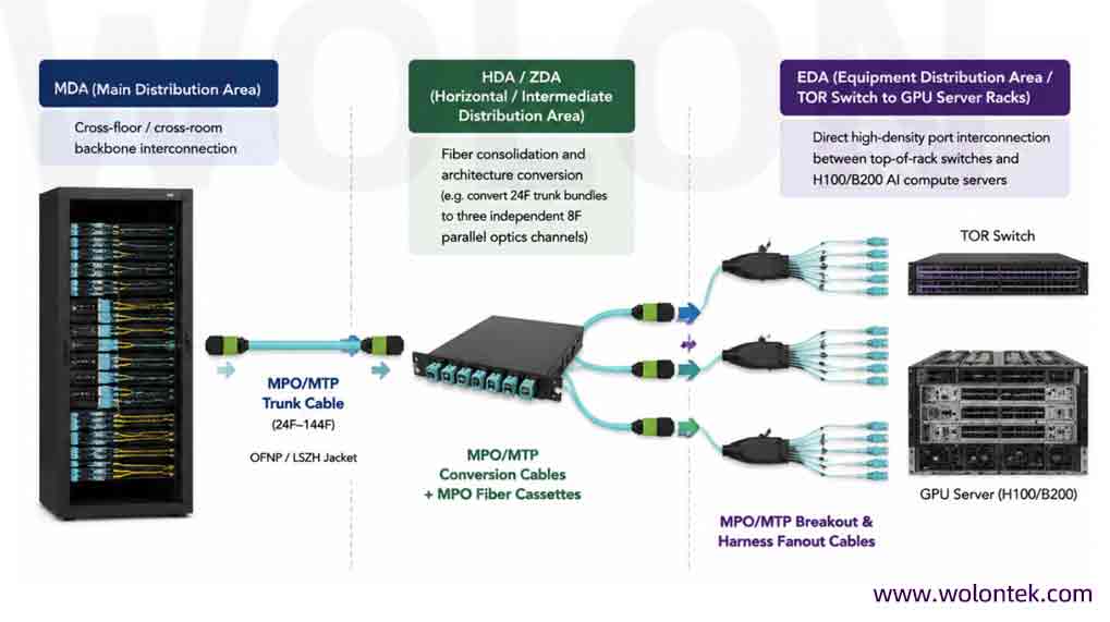
6. Five Critical On-Site Engineering Mistakes & Mitigation
Summarized from hundreds of WolonFiber hyperscale data center delivery projects, these five misconfigurations lead to costly downtime and hardware damage:
Mistake 1: Deploy heavy trunk cables as equipment patch jumpers
Consequence: Trunk cables feature thick rigid jackets and heavy tensile reinforcement. Direct mating to transceiver ports creates sustained shear force, causing port loosening, ferrule micro-displacement and rising insertion loss over time.
Correct Practice: Trunk cables terminate exclusively at patch panels; all equipment-side interconnections adopt flexible micro-breakout or harness fanout assemblies.
Real Project Case: A mid-size cloud data center deployed 24F trunk cables directly to 800G OSFP transceivers, triggering 15+ link error alarms within 30 days and requiring full cable replacement.
Mistake 2: Mismatch UPC flat-polish and APC 8° angled-polish connectors
Consequence: Multimode systems adopt UPC polish (black/blue/purple housings); single-mode parallel optics utilize APC polish (green housings). Mismatched polish creates air gaps at mating interfaces, severely degrading return loss and triggering link dropouts.
Visual Identification Rule: Green connector housings = APC; black, aqua or violet housings = UPC.
Mistake 3: Specify equal-length fanout legs for high-density switch racks
Consequence: When a single 24F MPO breakout splits into 12 LC duplex legs for 48-port switches, equal-length legs create extreme tensile stress on far-end ports and tight bending radii on near-end ports, violating optical fiber mechanical limits.
Correct Practice: Submit exact switch model numbers to manufacturers for custom staggered-length fanout leg production.
Mistake 4: Dry-wipe MPO ferrules without professional cleaning tools
Consequence: MPO ferrules integrate 8–24 densely packed fiber cores. Single 1μm dust particles block full core transmission, or get pressed into ferrule surfaces by guide pins to create permanent scratches.
Correct Practice: Utilize dedicated one-click MPO cleaners or cassette cleaning tools; perform endface inspection with fiber microscope before every mating operation.
Mistake 5: Skip gender verification during procurement
Consequence: Bulk orders of dual-female breakout cables cannot mate with female patch panel backside adapters; male-ended breakout cables damage internal transceiver guide pins during insertion.
Correct Practice: Confirm transceiver/panel gender specifications and lock female MPO ends for all direct equipment patch assemblies in purchase documentation.
7. Step-by-Step MPO/MTP Cable Selection Workflow
Follow this standardized decision tree for design and procurement of 800G/1.6T AI cluster physical layer cabling:
- Confirm line rate and optical architecture to lock fiber base framework
- Base-8: 400G DR4 / 800G DR8 / 800G SR8 parallel optics, 100% fiber utilization (preferred for new AI compute clusters)
- Base-12: Legacy 10G/40G duplex and 100G SR4 network retrofits
- Base-16: Next-gen 800G dual FR4 and 1.6T ultra-high-density transmission platforms
- Identify network hierarchy to select cable category
- Long-distance cross-area backbone interconnection → Female-to-Female Trunk Cable
- Switch port splitting to GPU server NICs → Breakout / Harness Fanout Cable
- Legacy 12F/24F trunk upgrade to Base-8 parallel optics → Conversion Cable
- Validate polarity and gender mating compatibility
- Direct transceiver connection: Specify female unpinned MPO ends
- All 400G/800G parallel optical links: Standardize Type B full-flipped polarity
- Interconnection with patch cassettes: Cross-check male/female pin configuration on panel rear adapters
- Specify jacket flame retardant rating per deployment environment
- OFNP Plenum: North America high-rise air ventilation plenum spaces, highest fire resistance standard
- LSZH Low Smoke Zero Halogen: Mainstream specification for EU and domestic hyperscale data centers
- OFNR Riser: Vertical inter-floor cable shaft routing
- Enforce factory testing and performance specificationsMandate full factory test reports for all pre-terminated assemblies:
- 3D interferometer inspection to verify core dip, radius of curvature and fiber height per IEC standards
- Elite low-loss grade MPO/MTP ferrules (max single connector insertion loss ≤0.35dB for single/multimode), reserved optical power budget for 800G/1.6T high-speed PAM4 links
8. Summary
Within modern 800G/1.6T hyperscale and AI compute data center optical networks, MPO/MTP Trunk, Breakout/Harness Fanout and Conversion cables deliver distinct, complementary roles to build scalable, stable physical layer topologies:
- Trunk Cables form the rigid, permanent backbone inter-distribution infrastructure
- Breakout & Harness Fanout Cables enable flexible high-density port splitting for edge GPU server access
- Conversion Cables serve as cost-effective transition media for legacy network upgrades, maximizing ROI of existing pre-installed trunk fiber assets
Mastery of their mechanical characteristics, polarity mapping rules and deployment limitations enables network architects and procurement teams to cut onsite rework costs, eliminate hardware damage risks, and build future-proof physical layer cabling systems fully optimized for 800G and 1.6T AI optical transmission.
What is the core difference between Harness Cable and Breakout Cable?
Breakout Cable is a general term for all one-to-many split fiber assemblies. Harness Cable is a subset of breakout cables, referring to short, compact fanout cables only used inside racks for patch panel-to-switch/server jumpers. All harness cables are breakout cables, but not all breakout cables qualify as harnesses.
Why Type B polarity is mandatory for all 400G/800G parallel optical links?
Type B fully flips fiber positions from Pin 1↔Pin N, which automatically aligns Tx lanes on one transceiver to Rx lanes on the remote device. It eliminates the need for extra A/B crossover patch cords, simplifies inventory and avoids human wiring errors common with Type A trunk systems. Type C is only for old duplex serial links and cannot support multi-lane parallel optics.
Can I use MPO trunk cable to directly connect 800G transceivers?
Not recommended and prohibited in formal engineering specs. Trunk cables feature thick, rigid jackets and heavy Kevlar reinforcement. Long-term direct connection to transceiver ports creates continuous shear stress, loosening ports and causing ferrule micro-displacement, which raises insertion loss and triggers PAM4 link errors. Only flexible micro breakout/harness cables are allowed for equipment direct patching.
When do I need Conversion Cable instead of replacing existing trunk cables?
Conversion cables are required during network upgrades when your pre-installed trunks are 12F/24F Base-12, while new 800G DR4/SR8 hardware adopts Base-8 architecture. Conversion cables split 24F trunks into three independent 8F channels, achieving 100% fiber utilization without re-running expensive backbone trunks.
What damage will UPC and APC mismatching cause?
UPC flat polish and APC 8° angled polish cannot form seamless contact. Air gaps at the mating surface drastically reduce return loss, introducing severe signal reflection. For single-mode 800G PAM4 links, reflection noise collapses the eye diagram and leads to constant link flapping or full outages. Multimode only uses UPC; single-mode parallel optics uses APC.
Do all high-density switches require staggered-length fanout legs?
Equal-length legs work for flat single-row adapter panels. For multi-row 48/64-port high-density switches (Cisco Nexus, Arista), staggered legs are mandatory. Equal legs overstretch far-end ports and create sharp bends on near-end ports, violating minimum bend radius limits and damaging fiber cores long-term.
Base-8 or Base-12, which one should I choose for new AI GPU clusters?
Base-8 is the standard for all new greenfield 400G/800G/1.6T AI clusters. Base-12 wastes 33.33% of fiber capacity for DR4/SR8 4-lane parallel optics, increasing infrastructure TCO. Base-12 is only acceptable for legacy network renovation projects.
What insertion loss grade should I specify for 800G PAM4 links?
Mandate MTP Elite Low Loss grade ferrules with single connector insertion loss ≤0.35dB. PAM4 signals have a fixed 4.8dB SNR penalty, leaving limited power budget for channel loss. Standard loss MPO connectors will exhaust optical margin and trigger DSP bit errors under high baud rates.
How to select flame retardant jacket material for data center cabling?
OFNP Plenum for North American plenum air duct deployments; LSZH low smoke zero halogen for EU, Asia and global hyperscale standard data centers; OFNR Riser only for vertical inter-floor cable shafts without plenum air circulation.
What is the correct MPO ferrule cleaning procedure before mating?
Dry wiping with tissue paper is forbidden. Use one-click MPO cleaning pens or cassette cleaners, then inspect all fiber endfaces via fiber microscope to eliminate 1μm dust particles. Dust trapped between ferrules will create permanent scratches on polished fiber surfaces.