
Upgrading a data center to 400G Ethernet is not a simple swap of optical transceivers. The transition to 400G fundamentally alters physical layer requirements. Because 400G utilizes PAM4 (Pulse Amplitude Modulation 4-level) signaling instead of legacy NRZ, the optical link loss budget is drastically reduced.
A single dirty ferrule or the wrong 400G MPO cable configuration will lead to Forward Error Correction (FEC) exhaustion and catastrophic packet loss.
To ensure error-free transmission across QSFP-DD and OSFP form factors, network architects must precisely match their transceiver types with the correct MPO fiber counts, polish angles, and ferrule grades. This engineering guide breaks down the strict procurement rules for 400G MPO cabling.
1. Matching the 400G MPO Cable to the Transceiver
Unlike 100G networks where a standard Base-12 MPO cable covered most scenarios, 400G introduces new parallel optic lane architectures. The type of 400G MPO cable you need depends entirely on the transceiver’s IEEE specification.
- 400GBASE-SR4 / DR4 (4 Lanes): These transceivers transmit 400G over 4 parallel lanes of 100G. They require a standard MPO-12 interface. However, they operate on a Base-8 configuration, meaning only the outer 8 fibers are active (4 for Tx, 4 for Rx), while the middle 4 fibers are dark.
- 400GBASE-SR8 (8 Lanes): This transceiver splits the 400G signal into 8 parallel lanes of 50G. It requires a high-density MPO-16 interface (a single row of 16 fibers). You must use a Base-16 MPO cable; a standard 12-fiber cable will not physically fit or function.
- 400GBASE-DR4 to 100G Breakouts: When bifurcating a 400G port to four 100G servers, you must specify an MPO-12 (Base-8) to 4x Duplex LC breakout cable.
2. The Shift to Base-8 and Base-16 Architectures
Deploying legacy Base-12 MPO trunk cables in a 400G environment creates immediate infrastructure bottlenecks.
If you plug a Base-12 cable into a 400GBASE-SR4 module, you are paying for 12 strands of glass but only utilizing 8. This 33% waste compounds rapidly across high-density patch panels, creating unnecessary cable bulk and complicating polarity management.
Modern 400G data centers mandate Base-8 infrastructure for 4-lane optics and Base-16 for 8-lane optics. This ensures 100% fiber utilization, streamlines Type B polarity mapping, and simplifies patching across the leaf-spine topology.
3. Strict Insertion Loss (IL) Budgets in PAM4 Networks
PAM4 modulation encodes two bits of data per symbol, doubling the data rate of NRZ. However, this creates a much smaller “eye diagram,” making the signal hyper-sensitive to optical noise and insertion loss (IL).
- The IEEE 802.3bs standard limits the total channel insertion loss for a 400GBASE-DR4 link (500 meters) to exactly 3.0 dB.
- Standard-grade MPO connectors typically exhibit >0.60 dB of loss per mated pair. If your link passes through multiple cassettes and patch panels, you will instantly exceed the 3.0 dB threshold.
To maintain stable link margins, 400G MPO cables must be specified with Low-Loss or Elite-grade MT ferrules. Procurement specifications should mandate a maximum insertion loss of 0.35 dB (0.10 dB typical) at the MPO interface, verified by individual 3D interferometer testing.
4. Single-Mode (APC) vs. Multimode (UPC) Polish Rules
Transceiver interface physical contact rules remain uncompromising at 400G. Mismatching the end-face polish will destroy the transceiver lenses.
- For 400GBASE-DR4 (Single-Mode / OS2): You must specify MPO cables with an APC (Angled Physical Contact) polish. The 8-degree angle minimizes back-reflection (Return Loss >60dB), which is fatal to single-mode lasers. These cables feature yellow jackets and green connector boots.
- For 400GBASE-SR4 / SR8 (Multimode / OM4 or OM5): You must specify MPO cables with a UPC (Ultra Physical Contact) flat polish. These feature aqua or lime-green jackets with beige or aqua connector boots.
5. Gender Mating Requirements (Pinned vs. Unpinned)
Almost all 400G QSFP-DD and OSFP parallel transceivers are equipped with Pinned (Male) MPO interfaces.
When purchasing a 400G MPO cable to plug directly into the switch port, the cable must be Unpinned (Female). Attempting to force a pinned cable into a pinned transceiver will crush the alignment pins and permanently damage the $1,000+ optical module.
Secure Your 400G Physical Layer CapEx
Scaling a 400G leaf-spine architecture requires uncompromising optical components. Relying on generic trade companies for high-speed physical layer infrastructure introduces unacceptable deployment risks and distributor markups.
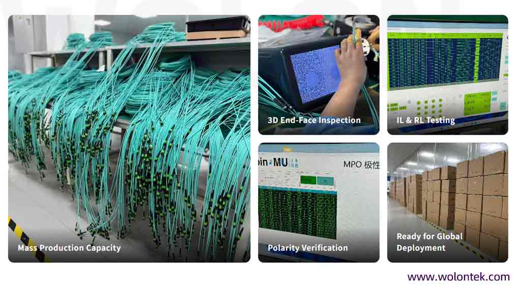
Operating a 400 to 500 employee manufacturing ecosystem directly in Optics Valley, WolonFiber provides factory-direct 400G MPO assemblies engineered for PAM4 tolerances. Every Base-8 and Base-16 cable is terminated with genuine US Conec MTP® Elite components, strictly maintaining IL <0.35dB. With massive automated capacity, we deliver fully 3D-interferometer tested trunk cables to global data centers in just 7 to 10 days.
Ensure zero packet loss and bypass the middleman.

Do I need a Type A or Type B MPO cable for a direct 400G connection?
If you are connecting two 400G parallel optic transceivers directly (e.g., switch-to-switch using 400GBASE-SR4), you must use a Type B (Cross-Over) MPO patch cord. Type B ensures that the Transmit (Tx) lanes on one module map perfectly to the Receive (Rx) lanes on the other. Type A (Straight-Through) cables are generally reserved for backbone extensions where a polarity flip is handled by a cassette down the line.
Can I reuse my existing Base-12 MPO trunk cables for a 400GBASE-DR4 upgrade?
Technically, yes, but it is highly inefficient. A 400GBASE-DR4 transceiver only utilizes 8 fibers (4 Tx, 4 Rx). If you plug a legacy Base-12 MPO cable into it, the outer 8 fibers will carry the signal, but the middle 4 fibers will remain permanently dark. To maximize your patch panel density and eliminate wasted optical glass, new 400G rollouts should be strictly standardized on Base-8 architecture.
What happens if I accidentally plug an APC MPO cable into a UPC transceiver?
Do not attempt this under any circumstances. Multimode 400G transceivers (SR4/SR8) use a flat UPC (Ultra Physical Contact) polish, while single-mode transceivers (DR4) require an angled APC (8-degree) polish. Forcing an angled APC ferrule against a flat UPC receptacle will instantly crush the fiber cores, creating a massive air gap and permanently destroying the optical lenses inside the transceiver.
Why is a 3.0 dB insertion loss budget so critical for 400G networks?
Unlike legacy 100G NRZ signaling, 400G Ethernet uses PAM4 (Pulse Amplitude Modulation 4-level). PAM4 doubles the data rate but significantly reduces the “eye diagram” opening, making the signal highly susceptible to optical noise. If your total cable link (including all patch cords, trunks, and cassettes) exceeds the IEEE 3.0 dB limit, the transceiver’s Forward Error Correction (FEC) algorithms will fail, resulting in dropped packets and link failure.