
Modern AI clusters and hyperscale data centers share a critical physical bottleneck: solid silica glass. As port speeds scale toward 800G and 1.6T, standard single-mode fibers (ITU-T G.652.D) hit insurmountable performance limits in latency, chromatic dispersion, and nonlinear signal distortion. For next-generation AI networking, the industry’s breakthrough solution is not improved glass—it is the complete removal of the solid glass core.
Hollow Core Fiber (HCF) propagates light through an air or vacuum channel instead of a solid silica core. This paradigm shift in waveguide physics eliminates fundamental silica-based limitations, redefining the design of latency-critical AI and high-performance computing networks. This guide breaks down HCF’s core working principles, its transformative impact on AI computing fabrics, and the key manufacturing engineering behind reliable, high-density HCF patch cord deployments.
What is Hollow Core Fiber (HCF)?
Hollow Core Fiber (HCF) is an advanced class of optical waveguide that transmits light through a central hollow channel—typically filled with air or a vacuum—rather than a traditional solid silica glass core.
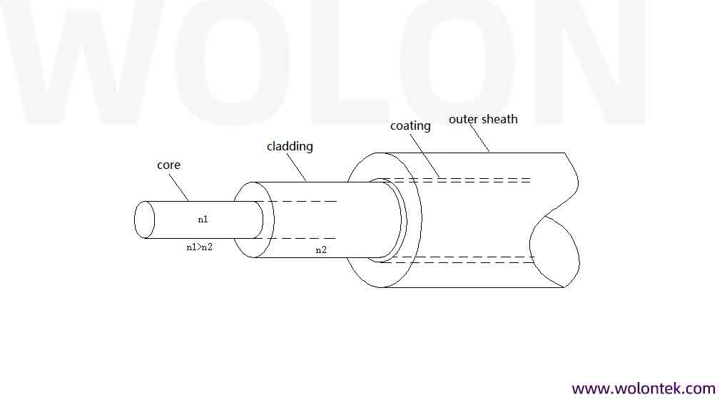
Unlike standard optical fibers that rely on total internal reflection within solid glass, HCF confines the optical signal inside the air cavity using a complex microstructure of microscopic glass capillaries in the surrounding cladding. By removing the solid glass from the light path, HCF allows optical signals to travel at nearly 99.97% of the absolute speed of light in a vacuum. This fundamental design eliminates the physical constraints of silica, drastically reducing network latency, suppressing nonlinear distortions, and expanding the usable transmission bandwidth for high-performance computing (HPC) and AI architectures.
The Physics of Vacuum-Speed Light Transmission
In standard Single-Mode Fiber (SMF), optical signals travel through a solid silica glass core with a refractive index (n) of approximately 1.468 at a wavelength of 1550 nm. The velocity of phase propagation is governed by the fundamental physics equation:
$$v = \frac{c}{n}$$
Where $c$ represents the speed of light in a vacuum (299,792.458 km/s). Consequently, light inside standard solid glass is slowed to roughly 204,218 km/s. This delay introduces a structural latency profile of approximately 4.897 µs/km.
In contrast, Hollow Core Fiber replaces the solid glass core with an air cavity possessing a refractive index of approximately 1.0003. This allows optical signals to propagate at 99.97% of the speed of light in a vacuum, reducing the physical layer latency profile to 3.337 µs/km.
The absolute latency delta between solid-core fiber and HCF is 1.56 µs/km. In latency-bounded architectures, this ~32% reduction eliminates a major source of delay in the physical interconnect layer.
Solid-Core vs Hollow Core: Core Engineering Benchmarks
| Parameter | Standard Solid SMF | Hollow Core Fiber (HCF) | Engineering Impact |
| Refractive Index (n) | ≈1.468 | ≈1.0003 | Unlocks near-vacuum light transmission speeds. |
| Latency Profile | 4.90 μs/km | 3.34 μs/km | ~32% reduction in physical layer propagation delay. |
| Nonlinear Refractive Index (n₂) | ≈2.6 × 10⁻²⁰ m²/W | ≈3.0 × 10⁻²³ m²/W | ~1,000× lower nonlinearity, supporting high-power DWDM. |
Why Modern AI Data Centers Mandate HCF Deployment
A 32% per-kilometer latency reduction seems marginal for single server links, yet it becomes a transformative advantage for distributed machine learning and large-scale GPU cluster workloads. Modern AI training relies heavily on synchronous parallel processing protocols such as All-Reduce and All-to-All communication. In these synchronized architectures, the entire compute cluster must wait for the slowest node to complete data exchange before initiating the next training iteration.
Real-World AI Cluster Impact For a 5-kilometer InfiniBand link between data center halls, standard solid fiber delivers a round-trip latency of ~49 μs, while HCF reduces this round-trip delay to just 33 μs. Across millions of continuous training iterations, this 16 μs per-cycle latency saving eliminates massive GPU idle time, accelerates model convergence, and cuts overall cluster power consumption significantly.
Beyond latency optimization, HCF’s ultra-low nonlinear coefficient eliminates power-induced signal distortions including Four-Wave Mixing (FWM) and Self-Phase Modulation (SPM). This allows network engineers to deploy higher optical launch power and denser DWDM channel grids without crosstalk or signal degradation, maximizing bandwidth utilization for 800G/1.6T high-speed fabrics.
HCF Structural Evolution: From Legacy PBGF to Modern NANF
Early hollow core fiber designs faced critical limitations in loss performance and manufacturability. Today’s commercial HCF reliability and wide-scale data center adoption are enabled by a key shift in microstructure design, from legacy Photonic Bandgap Fiber to advanced Nested Antiresonant Nodeless Fiber (NANF).
Microstructure Performance Comparison
| Feature | PBGF (Legacy HCF) | NANF (Modern Industry Standard) |
|---|---|---|
| Internal Structure | Complex honeycomb air hole lattice | Nested, non-touching glass capillaries |
| Attenuation Limit | 1.0 – 2.0 dB/km | ≤0.15 dB/km (near theoretical limits) |
| Usable Bandwidth | Narrow (<100 nm) | Ultra-wide (covers O, S, C, L bands) |
| Key Drawbacks | High surface scattering loss, narrow operational spectrum | Zero nodal scattering, low loss, full-band transmission |
Unlike the loss-prone honeycomb lattice of PBGF, NANF utilizes a single ring of standalone, non-contact glass capillaries surrounding the central air core. Leveraging Fabry-Perot antiresonance principles, the thin capillary walls reflect optical signals back into the air core with near-zero leakage, delivering ultra-low attenuation and full-spectrum transmission for high-speed data center networks.
Core Engineering Challenges: Manufacturing Reliable HCF Patch Cords
Long-distance HCF trunk deployment is well-established, but high-density rack-level connectivity requires terminating fragile air-core fiber into standard LC, SN, and MTP/MPO connectors. Factory production of high-performance HCF patch cords overcomes three critical technical barriers:
1. Hermetic Core Sealing (End-Cap Technology)
Exposed open HCF capillaries absorb moisture and airborne dust via capillary action, causing immediate signal attenuation and permanent fiber degradation. Premium-grade HCF patch cords solve this via precision laser-fused solid silica end-caps. A 100 μm ultra-pure glass window is permanently fused to the cleaved HCF end, creating a fully hermetic seal that protects the internal microstructure while enabling unobstructed optical beam transmission.
2. Mode Field Diameter (MFD) Mismatch Resolution
Standard high-speed transceivers are optimized for a 9 μm mode field diameter (MFD), while modern NANF air cores feature a far wider MFD of 15–30 μm. Direct coupling causes severe transverse misalignment loss and signal attenuation. Professional factory-terminated HCF assemblies integrate high-precision Mode Field Adapters (MFAs) to reshape the transceiver beam profile, perfectly matching the air core dimension and maintaining stable low insertion loss.
3. Back-Reflection & Return Loss Suppression
The refractive index boundary between the air core (n≈1.0) and solid silica end-cap (n≈1.45) generates Fresnel reflection, reflecting ~3.4% of optical power back toward the transceiver. This back-reflection destabilizes 400G/800G/1.6T DFB and EML lasers, causing signal jitter and link failure. To mitigate this, premium HCF patch cords adopt strict 8° Angled Physical Contact (APC) polishing paired with nanometer anti-reflective (AR) thin-film coatings, boosting return loss performance to above 60 dB for stable high-speed transmission.
Enterprise-Grade HCF Deployment with WolonFiber
HCF patch cords cannot be field-terminated or spliced with standard arc fusion equipment—their delicate air-core microstructure requires ultra-precise, controlled factory manufacturing. This high technical barrier often creates supply chain bottlenecks for large-scale AI infrastructure upgrades.
Based in Wuhan Optics Valley, WolonFiber (wolontek.com) bridges cutting-edge HCF waveguide technology and real-world data center deployment. We deliver custom, high-reliability HCF patch cords and MPO high-density assemblies tailored exclusively for latency-sensitive AI compute fabrics, moving beyond generic off-the-shelf optical components.
Our full-process manufacturing quality control guarantees consistent, production-grade HCF performance:
- Automated CO₂ Laser Splicing: Delivers flawless, low-loss hermetic end-cap sealing without microstructure damage
- 100% 3D Interferometer Testing: Strict geometric calibration of APC angles and ferrule radii to eliminate transceiver damage and link instability
- Customized Rack-Level Design: Optimized cable lengths and breakout configurations to fit precise switch rack layouts, eliminating cable slack and airflow blockages in high-density server environments
Future-Proof Your AI Network Infrastructure
Legacy solid-core silica fiber has become the hard ceiling for modern GPU cluster throughput and AI training efficiency. For 800G/1.6T fabric upgrades and large-scale AI cluster deployments, HCF physical layer optimization is no longer optional—it is essential.
Consult our professional engineering team to obtain official 3D interferometer test reports, customized technical specifications, and low-loss HCF patch cord prototypes for your next-generation AI data center project.
Can Hollow Core Fiber be spliced to standard solid-core single-mode fiber in the field?
No. Splicing HCF to standard solid fiber using traditional field arc fusion splicers will collapse the delicate internal air capillaries, resulting in massive signal loss. Terminations and transitions must be performed in a factory setting using highly controlled CO₂ lasers and specialized Mode Field Adapters (MFAs).
Is Hollow Core Fiber more fragile than traditional optical fiber?
While the internal microstructure of HCF is highly complex, the external jacketing of commercial HCF trunk cables and patch cords is just as robust as standard fiber assemblies. However, network technicians must strictly adhere to the manufacturer’s bend radius limits to prevent micro-bending losses or capillary deformation.
Why do HCF patch cords require an APC (Angled) connector?
HCF patch cords rely on a solid glass “end-cap” to seal the hollow core. The transition between the air core and the solid glass cap causes Fresnel reflection. An 8-degree APC polish ensures that any reflected light is deflected into the cladding rather than traveling back into the transceiver, keeping the Return Loss (RL) safely above 60 dB.
Does Hollow Core Fiber support DWDM (Dense Wavelength Division Multiplexing)?
Yes, exceptionally well. Because HCF guides light through air, its nonlinear refractive index is roughly 1,000 times lower than solid silica. This near-zero nonlinearity allows operators to pump significantly higher optical power into dense WDM channels without triggering signal distortions like Four-Wave Mixing (FWM).