
Installing fiber underground is one of the most durable ways to protect a network’s backbone — when it’s done right. Direct-burial fiber cable eliminates the need for continuous conduit runs and can be faster and more cost-effective on long, open runs. But because the cable sits in soil exposed to moisture, load, rodents and excavation risk, planning and execution must be careful. This guide explains the common cable constructions, when to choose direct-burial, a practical installation workflow, and the best practices that minimize downtime and future repair costs.
What “direct-burial” means
A direct-burial fiber cable is manufactured and jacketed to be installed straight in the ground without continuous conduit protection. Compared with conduit-and-pull methods, direct-burial can reduce materials and civil-work time on long point-to-point runs, and is widely used for campus, rural and intersite links. However, it’s typically chosen only when the route is predictable and when designers accept the trade-offs: deeper trenching, special backfill and upfront protection (armor, tape, tracer wire) to reduce future risk.
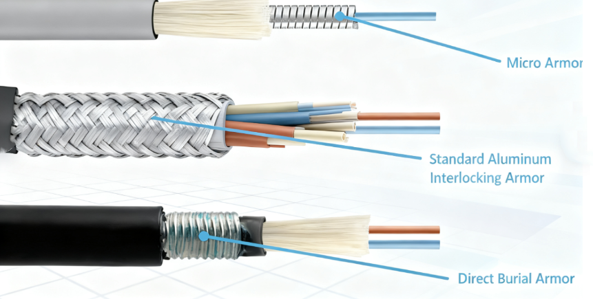
Types of direct-burial fiber cable
There are a few common constructions you’ll see in the field:
Loose-tube, gel-filled (or gel-free) outdoor cable — fibers live inside gel-blocked or water-swell tubes inside a central core. Loose-tube cables are common for outdoor, long-run applications because the tube protects fibers from microbending and water intrusion.
Armored direct-burial — a metal (usually corrugated steel) armor layer under the outer jacket gives strong crush and rodent protection; used where mechanical risk is higher (road crossings, rocky soil).
Tight-buffered / breakout-style — used where individual fibers need easy termination near buildings; less common for long, unprotected direct-burial runs.
Gel-free, water-blocked designs — modern cables use superabsorbent tapes or water-blocking powders instead of messy gel; these are easier to handle and repair in the field.
Choosing the right construction depends on distance, expected mechanical stress, soil chemistry, and whether you’ll pull individual fibers later.
Key installation considerations (planning phase)
Survey and route planning. Mark existing utilities and use local utility-locate services before digging (in the U.S., use the 811 service). Avoid high-traffic excavation zones and known rock or frost heave areas.
Select depth and protection to local codes. Minimum cover recommendations vary by standard and location — many manufacturers and network operators recommend 30 inches (≈77 cm) or more of cover for direct-buried fiber, with greater depth at roadway crossings and in freezing soils; local electrical codes (NEC/municipal rules) set minimums and should be checked before finalizing depth.
Conduit at critical points. Even on a mostly direct-bury route, use short sections of rigid conduit or handholes at road crossings, intersections and building entrances to protect against concentrated loads and to enable easier future access.
Trenching, plowing and mechanical installation methods
Two common methods are manual/mechanized trenching and plowing:
Trenching is used when precise placement, multiple cables, or complex terrain requires hand or machine-dug trenches. It is slower but gives control for bedding and warning systems.
Plowing is faster for long, linear rural routes; the plow opens a narrow slot and lays cable in a single pass. Plowing is efficient but offers less control over bedding and immediate backfill quality. The method should be chosen based on soil conditions, existing obstacles and required cable protection.


Best practices during placement
Use a sand/small-scree bedding layer. Place 2–4 inches of fine sand or screened bedding under and over the cable for cushion and to reduce rock penetration risk.
Install warning tape and tracer wire. Bright warning tape buried 6–12 inches above the cable alerts future excavators; a continuous tracer wire — insulated and accessible at handholes — lets locators find the buried run without disturbance. These measures dramatically reduce accidental strikes.
Maintain separation from electrical conductors. Observe local code for minimum horizontal and vertical clearances from power lines; separation minimizes induced current risk and simplifies maintenance.
Use armored cable or rodent/rodent-resistant jacket in high-risk areas. Where rodents, heavy foot/vehicle loads or rocky soil exist, choose armored or specially-jacketed cable.
Testing, documentation and handover
Pre-close testing. Before final backfill, perform an OTDR trace and attenuation tests to confirm fiber continuity and loss figures; record splice locations.
As-built records. Keep accurate GIS or plan drawings showing depth, route, splice points, and handhole locations — this reduces time and cost for future work.
Long-term maintenance and repair considerations
Design with repairability in mind: handholes spaced for future splicing, spare fibers or microducts for adding fibers later, and accessible tracer wires reduce future restoration time. For critical links, consider redundant routing so a single dig or local failure won’t isolate services.
Common mistakes to avoid
-
Shallow burial to save cost — this increases the chance of landscaping or construction damage.
-
Skipping warning tape or tracer wire — most accidental strikes occur where no marker exists.
-
Not testing before final backfill — finding a bad splice after full backfill is far costlier.
Quick installation checklist
-
Route survey + locate existing utilities.
-
Choose cable type (armored/loose-tube/gel-free) for environment.
-
Plan depth and protection per local code and manufacturer guidance.
-
Trench/plow with sand bedding, place cable, install tracer wire and warning tape.
-
Test (OTDR, power meter), document as-built, close trench.
WOLON product note

For installers seeking matched components, WOLON offers a range of optical transceivers and fiber accessories engineered to work with buried networks — singlemode transceivers for long-haul links, ruggedized MPO/MTP jumpers, and armored outdoor patch assemblies. WOLON modules are factory-tested for low insertion loss and consistent wavelength performance, making them a reliable choice when you need components that stand up to outdoor installations.
