
In the modern enterprise, the network is the business. Yet, while companies spend millions on servers and switches, they often neglect the physical layer that connects it all.
Structured Cabling is not just about keeping wires tidy. It is a standardized architecture (defined by TIA/EIA-568) that dictates how a building should be wired to ensure predictability, performance, and safety.
We will dissect the Six Essential Subsystems of a Structured Cabling System (SCS), explaining the engineering logic behind Entrance Facilities, Backbone hierarchies, and Horizontal limitations—enriched with insights from our factory floor.
What is Structured Cabling System(SCS)?
Structured Cabling System (SCS) is not just “running wires.” It is a standardized architecture for designing and installing a cabling infrastructure that is flexible and future-proof.
Think of it like the electrical grid in your house. You don’t run a dedicated extension cord from the power plant to your toaster. You have a main breaker box, circuits in the walls, and standardized outlets in every room.
Structured cabling works the same way. Instead of running point-to-point cables (which leads to the “spaghetti mess”), you install a permanent, organized infrastructure of patch panels and trunks. This allows you to connect any device (PC, Phone, Camera) to any port without ripping open the walls.
The 6 Basic Elements of a Structured Cabling System
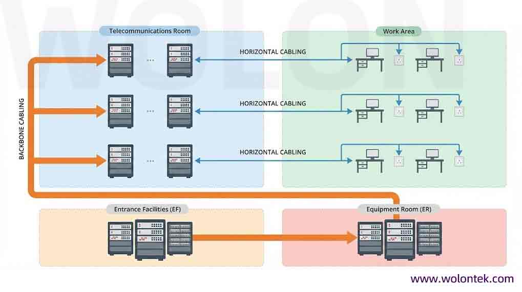
According to international standards (TIA-568), a proper structured cabling system is divided into six logical chunks. As a manufacturer, we design specific products for each of these zones.
1. Entrance Facilities (EF): The Fortress Gate
The Entrance Facility (EF) is the critical demarcation point where the outside world (ISP / Telecom Provider) meets your private building network. It is the “border control” of your data.
Core Function: It houses the transition from outdoor plant cables (which are often gel-filled and armored) to indoor-rated fire-retardant cables.
Critical Protections:
- Grounding & Bonding: This is non-negotiable. The EF contains the Primary Bonding Busbar (PBB) which establishes a safe electrical path to earth ground. This protects your expensive switches from lightning strikes and electrical surges entering via the copper lines.
- Shielding: Equipment here shields the internal network from external Electromagnetic Interference (EMI) and Radio Frequency Interference (RFI).
- Surge Protection: Devices are installed here to arrest power spikes before they travel inland to your server room.
⚙️ Wolon Factory Insight: Never run “Outdoor Rated” (PE Jacket) cable deeper than 50 feet (15m) into the building. It is flammable. The EF is where you must splice outdoor fiber to indoor (Riser/Plenum) fiber to meet fire codes.
2. Equipment Room (ER): The Central Nervous System
The Equipment Room (ER), often called the Main Distribution Frame (MDF), is the most complex space in the building. It acts as the central hub where the backbone cabling from the EF distributes to the rest of the campus.
What Lives Here: This room houses the “Core” layer equipment—massive chassis switches, main servers, SANs (Storage Area Networks), and the main cross-connects (MC).
Environmental Control: Because active equipment generates massive heat, the ER requires dedicated HVAC systems to maintain strict temperature (18°C-27°C) and humidity (40%-60%) levels to prevent static discharge or corrosion.
Cable Management: High-density patch panels organize the massive influx of cabling.
- Backbone Cabling arrives here from other floors.
- Horizontal Cabling arrives here from nearby workstations.
⚙️ Wolont Factory Insight: In the ER, “Vertical Cable Management” is as important as the cable itself. Without wide vertical managers on the sides of the racks, the sheer weight of hundreds of Cat6a cables can crush the bottom cables, causing “Alien Crosstalk” and packet loss.
3. Backbone Cabling: The Vertical Spine
Backbone cabling is the highway that connects your Equipment Room (ER) to your Telecommunications Rooms (TR). It handles the aggregated traffic of the entire building. In modern Data Center designs, this is often strictly defined by hierarchies: Main Cross-Connect (MC), Intermediate Cross-Connect (IC), and Horizontal Cross-Connect (HCC).
We divide Backbone Cabling into two distinct Subsystems:
Cabling Subsystem 2 (Building Backbone)
Definition: The link between the Horizontal Cross-Connect (HCC) on a floor and the Intermediate Cross-Connect (IC).
Common Name: “Riser Cabling.”
Media Type: Typically Multi-mode Fiber (OM3/OM4) for data or high-pair-count Copper (Cat3/Cat5e) for voice.
Cabling Subsystem 3 (Campus Backbone)
Definition: The link between the Intermediate Cross-Connect (IC) and the Main Cross-Connect (MC).
Common Name: “Campus Cabling.”
Media Type: Almost exclusively Single-mode fiber (OS2) due to the longer distances required between buildings.
⚙️ Wolon Factory Insight: When designing Backbone, Fiber is King. While copper can do 10G over short distances, fiber (OM4/OS2) is immune to EMI and has vastly superior bandwidth. We recommend running hybrid fiber trunks (12-strand or 24-strand MPO) for all Subsystem 2 & 3 links to future-proof for 40G/100G.
4. Telecommunications Room (TR) & Enclosures (TE)
The Telecommunications Room (TR) is the floor-level distribution point. Think of it as a satellite office for the main Equipment Room.
Function: It is the meeting place where the vertical Backbone (coming from the ER) is cross-connected to the Horizontal cabling (going to the desks).
components: It houses floor switches, patch panels, jumpers, and patch cords.
Cross-Connects:
Interconnection: Direct patching (Switch Port -> Patch Panel).
Cross-Connection: Patch Panel to Patch Panel (More flexible).
Organization: Proper labeling (ANSI/TIA-606-B standard) here is critical. If a user on the 3rd floor loses internet, the technician comes here first.
5. Horizontal Cabling: The Last 90 Meters
Horizontal Cabling extends from the TR/TE patch panel to the individual outlet on the wall at the user’s desk. It is called “horizontal” because it typically runs along the ceiling or raised floor.
The Golden Rule: The maximum distance is 90 meters (295 ft) for the permanent link. This leaves 10 meters for patch cords (5m at the TR + 5m at the desk) to reach the 100-meter Ethernet channel limit.
Cable Types:
Cat6: The standard for Gigabit.
Cat6a: Mandatory for 10 Gigabit or high-power PoE++ (802.3bt).
Fiber: Fiber-to-the-Desk (FTTD) for high-security applications.
Components: Solid conductor cables (inside walls), Keystone Jacks (at the wall), and Patch Panels (at the TR).
⚙️ Wolon Factory Insight: Service Loops Matter. We always advise installers to leave a “Service Loop” (3-5 meters of extra coiled cable) in the ceiling above the TR. If you ever need to move the rack or re-terminate the patch panel, that extra slack is a lifesaver.
6. Work Area (WA): The Human Interface
The Work Area (WA) is the final 5 meters of the system—the space where the human meets the network.
Scope: Starts at the wall faceplate and ends at the user’s device (Laptop, IP Phone, Printer, Wireless AP).
Key Components:
- Faceplates & Surface Mount Boxes.
- Patch Cords: Stranded copper cables for flexibility.
- Multi-User Telecommunications Outlet Assemblies (MUTOA): For open-office clusters.
Integration: This area often includes power outlets and surge protectors to ensure active equipment safety.
⚙️ Wolon Factory Insight: The Weakest Link. 50% of network failures happen in the Work Area. Why? Because users buy cheap, low-quality patch cords from Amazon. Ensure your Work Area patch cords match the category of your wall cabling (e.g., use Cat6a cords with Cat6a wall jacks) to maintain channel performance.
The Advantages of a Structured Cabling System
Why spend the money to organize everything? Why not just drill holes and run cables where needed? Here is the business case.
1. Scalability (Future Growth)
Today you have 10 employees. Next year you might have 50. With a structured cabling system, you don’t need to re-wire the building. You simply patch a new cord into an existing port in the patch panel. It’s “Plug and Play” for growth.
2. Flexibility (MACs – Moves, Adds, Changes)
In the corporate world, people move desks all the time.
Without SCS: You have to pull a new long cable through the ceiling.
With SCS: You just unplug their patch cord in the server room and plug it into the port corresponding to their new desk. What used to take 2 hours now takes 2 minutes.
3. Reliability & Performance
“Spaghetti cabling” blocks airflow in racks, causing switches to overheat. It also puts stress on the cables, leading to bent pins and broken cores. Organized structured cabling keeps airflow clear and cables safe, drastically reducing network downtime.
4. Easy Troubleshooting
When the network is down, time is money.
Messy Network: Trying to trace a loose cable through a tangled ball of wire is a nightmare.
Structured Network: Everything is labeled (e.g., “Port A-01”). The technician looks at the diagram, finds the faulty port, and fixes it instantly.
5. Cost Effectiveness (TCO)
Yes, the initial installation cost (CapEx) of structured cabling is higher than just throwing wires over the ceiling tiles. However, the Operational Cost (OpEx) is significantly lower. You save money on maintenance, you save money on upgrades (Cat6a is good for 10+ years), and you save money by avoiding downtime.
Conclusion
Structured cabling is not just an expense; it is a 15-to-20-year investment in your building’s digital asset.
Whether you are building a new office in Dallas or retrofitting a warehouse in Dubai, the quality of your copper and the logic of your design will determine your network’s speed for the next decade.
Building a Network You Can Trust? Don’t settle for cheap copper or confusing layouts. Wolontek manufactures the entire ecosystem—from the bulk Cat6a cable in the walls to the patch panels in the rack.